


.svg)


Integrations can take two forms:
- Batch integrations—Collect, store, and process large amounts of data with basic, unchanging parameters.
- Real-time integrations (using REST based Web services)—Import and export data, such as discrete transactions, between systems as part of an operational business process.
Interoperability Quick Start enables you to:
- Import data from a spreadsheet—Select the Data Import Quick Start button, specify the CSV file you want to use and the table where you want to import the data, then save the record. The data mappings subtable is automatically populated with the data from the spreadsheet. Complex data types, such as table lookups, name, and address fields, require you to fill out the Mapping Type and Mapping Sub Type in the mappings subtable.
- Export data from a platform table—Select the Data Export Quick Start button then specify the table you want to export data from, the export format, and the data source type. A record is created in the Data Export Definitions application.
Interoperability applications
Interoperability applications include:
- APIs and endpoints
Application Programming Interfaces (APIs) are the rules which define how a system, also known as a client, can communicate and share resources with the server's API. An endpoint is the location of the information which is being requested by the client, often a URL, and is a component of an API.
- Events
Events, also known as event emissions and subscriptions, communicate changes that occur in business data to external targets and logic blocks.
- Connectors
Connectors facilitate communication between external systems and Nextworld. You can use them to send and receive data, or to initiate logic in an external system, such as J.D. Edwards.
- Webhooks
External systems send webhook notifications into Nextworld when events occur. This allows business logic within Nextworld to execute in response to those events.
- Model Context Protocol (MCP)
Model Context Protocol (MCP) is an open protocol standard for AI integrations. It enables you to build secure, standardized connections between organizational data and AI consumers, such as large language models (LLMs), without requiring custom integrations for each system.
- Environment overrides
Use environment overrides to override previously configured values in a specific environment. Environment overrides are used for data imports, data exports, endpoint definitions, and event definitions.
- Messages
Application developers, system administrators, and implementation teams configure the system to automatically send messages or notifications when message events are completed.
- Data imports
Data imports enable you to import external data into internal platform tables. Imports can be done as part of new environment implementation, or as recurrent processes.
- Data export process
Application developers and system administrators use multiple applications when exporting records from Nextworld. You must configure the data to export, export the records, and view a history of each export. Exported records can be downloaded as a generic file type or sent directly into an external system.
- List Lookup Cross Reference Utility application
Application developers use the List Lookup Cross Reference Utility application to create cross references for values which are represented differently between Nextworld and an external system, but are inherently the same. Cross references can change an external value to a Nextworld value in an import, or change a Nextworld value to an external value in an export.
- File Location Setup application
Application developers use the File Location Setup application to connect Nextworld to external systems. Data source records are used in both data import and data export definitions to seamlessly integrate data between systems.
APIs and endpoints
Application Programming Interfaces (APIs) are the rules which define how a system, also known as a client, can communicate and share resources with the server's API. An endpoint is the location of the information which is being requested by the client, often a URL, and is a component of an API.
Servers typically have many different APIs, and each API can allow access to multiple types of resources on the server. For example, Avalara is a cloud-based tax software which many systems, including Nextworld, use for tax calculations and compliance. Avalara has many APIs, such as an API for cross-border transactions, and another for short-term property rental tax compliance. The API for short-term property rentals has resources for VRBO, AirBNB, and FlipKey available at the same endpoint location.
APIs work by a client sending a request to the API for information or for a service, then the API sending a response back to the client. Nextworld uses a type of API called REST APIs, which designate an HTTP request method, such as GET, PUT, or DELETE, to indicate what type of action the API request is performing. For example, an API request with a GET HTTP method is used to fetch data, while an API with a PUT HTTP method is used to update data.
The diagram below illustrates how a client sends a request to an external server's API:
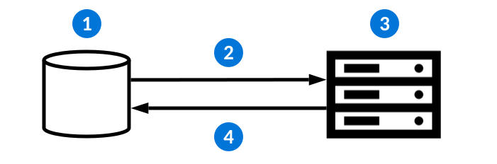
| Action | Example | |
|---|---|---|
 | The client initiates a request to the external server's API. | The Supplier Invoices application has a Calculate Tax form action. When selected, a logic block initiates an endpoint request. |
 | A request is sent to an API which contains the:
| The endpoint definition initiates a request to Avalara for a tax calculation. |
 | The API receives the request. | Avalara's tax calculation API receives the request. |
 | The external system sends a response back with a:
| Avalara's API sends a response with the requested tax calculation back to Nextworld. Logic blocks then use the provided response body to populate fields in the Supplier Invoices application. |
Endpoint request and response options for calling external API endpoints are configured in the Endpoint Definitions application. Learn more in Outbound endpoint configuration overview.
To learn more about external systems requesting information from Nextworld APIs, see the Inbound endpoint requests topic.
Correlation IDs
Correlation IDs are a unique identifier that enable you to track multi-system updates resulting from a single user action. The nwCorrelationId system field is automatically associated with processes such as webhooks, workflow transitions, jobs, events, summary tables, and inbound and outbound endpoint calls. If the Correlation ID on a Nextworld process is empty, the system generates one and logs it on all associated processes.
For example, an external system could make an endpoint call into Nextworld that includes a nwCorrelationId. This call results in a chain of processes including a workflow transition, background task, and an endpoint call to a third-party provider. Records logged in the Workflow Queued Transition Inquiry, Jobs, and Endpoint Logging applications would contain that correlation Id value, and the outbound endpoint call could optionally include it in the request payload. This is useful for identifying where and why a process failed.
Inbound endpoint calls have nwCorrelationId available in the Request Header. More information is available in the Endpoint Documentation accessible from the Sidebar menu under Integrations. You must navigate to a dashboard page before opening the menu to see the Integrations section.
Outbound endpoint calls can map nwCorrelationId in the Endpoint Definitions application. It may be selected in the Request Header, Request Body, or Query Parameters by navigating to the Request page and adding an entry where the type is Correlation ID.
Outbound endpoint configuration overview
Configure outbound endpoint requests with the Endpoint Definitions application, Logic Block Builder, and other endpoint applications. Endpoint requests enable the Nextworld Platform to communicate with external systems.
Configure your endpoint request
To configure your endpoint definition, you must create a new record in the Endpoint Definitions application, then:
- Select the type of endpoint, endpoint location, request authentication type, and request time out options. Learn more in Endpoint general configuration.
- Configure the headers, query parameters, and payload that are sent to an external REST API system as part of an endpoint request. Select whether your request is a File or JSON request type. Learn more in Endpoint request configuration.
- Configure your response set and response codes. Learn more in Endpoint response configuration.
Initiate your endpoint request
Once your endpoint definition is configured, you must use logic blocks to configure the criteria for when it is initiated. For example, you could initiate the endpoint request when a user selects a form action or field action. In the Logic Block Builder, configure a transactional logic block which calls the Call External Endpoint action. Learn more in Call External Endpoint action
Review errors
Use the Endpoint Log Inquiry application to review log records which indicate if an endpoint request was successful or failed. Learn more in Endpoint Log Inquiry application.
Endpoint general configuration
Configure the type of endpoint, HTTP method, authentication, and timeout options on the General page of the Endpoint Definitions application.
Endpoint Definitions
To configure your endpoint request, in the Endpoint Definitions application, on the General page, you must:
- In the Type field, select your endpoint type. Options include:
Method—Calls in a logic block and performs an action relevant to the business process.- This endpoint type can specify a
Token Creationendpoint as its Request Authentication Type. When this configuration option is selected, the Token Creation endpoint is automatically called first by the logic block.
- This endpoint type can specify a
Token Creation—Establishes a session with an external system. A request to the token endpoint is used to exchange an authorization code for an access token. Multiple endpoints can have the same token creation endpoint as their Request Authentication Type. For example, if you need to call a series of endpoints in a logic block, then they all re-use the same token.Token Release—Releases a session with an external system.
- Select the the HTTP Method. This indicates what type of action the API request is performing, such as GET, POST, or PUT.
- Select the Request Authentication Type. The type of authentication needed is dictated by the server you are requesting information from. This can be one, or many, types of authentication. Each authentication type requires different configuration steps. Learn more in Endpoint authentication options.
- Optionally, select the length of time before a request times out, the number of times a request is attempted, and how long to wait before attempting another request attempt.
- Optionally, select the Enable Logging checkbox to enable endpoint logging. When selected, a log is created for every interaction in the endpoint. When cleared, logs are only created for failed requests.
- Select whether the endpoint only logs failed attempts, or if it logs every request attempt, response, and failure. View log records in the Endpoint Log Inquiry application.
Once you have configured the General page of your definition, you must define your Request and Response information. Then, you'll configure a transactional logic block which uses the Call External Endpoint action to initiate your endpoint request. Learn more in:
Endpoint authentication options
Nextworld supports multiple authentication types for endpoint request calls, including OAuth 2.0, JSON Web Tokens, and secrets. The type of authentication used in your endpoint request is dictated by the server you are requesting information from. This can be one, or many, types of authentication.
Select your authentication type in the Request Authentication Type field, on the General Configuration page of your Endpoint Definitions application record. Each authentication type has different requirements, as seen in the subheadings below.
No Auth
The endpoint request does not require authentication. No further configuration is required.
Basic Auth
Requires a verified username and password, known as a secret, to access a data resource. Secrets are configured as Key-Value pairs in the Endpoint Secret Setup application. Navigate to the application from the Navigation Menu or select the Configure Secret field action. Learn more in Endpoint Secret Setup application.
You can optionally configure a logic block to automatically update the endpoint secret at set intervals. Learn more in Automatically update endpoint secrets.
Token
Requires another configured endpoint to generate a token that is then used to authenticate this endpoint definition. Reference the endpoint definition that retrieves the token.
OAuth 2.0
Requires authentication through a third-party website to grant access. The authentication provides an access token which is used for subsequent requests from our platform to the responding server. OAuth grant types include:
Authorization Code—Retrieves an access token once users sign into the external system. Nextworld exchanges an authorization code for the access token which is stored in the OAuth record.Refresh Token—Retrieves only a refresh token.Client Credentials—Obtains an access token outside of the context of a user. This is typically used to access resources about a user rather than to access a user's resources. Multiple options are supported, including:Client Secret—The client ID and secret are sent to the token endpoint in exchange for an access token. You can optionally configure a logic block to automatically update the secret at set intervals. Learn more in Automatically update endpoint secrets.JWT Assertion—The client authenticates using a JWT client assertion defined in the Endpoint JWT Setup application.
OAuth is configured in the OAuth Setup application. Navigate to the application from the Navigation Menu or select the Configure OAuth field action. Learn more in OAuth Setup application.
JSON Web Token
Requires a JSON Web Token be sent to our platform from the responding server to authenticate subsequent requests from our platform. JSON web tokens are configured in the JWT Setup application. Learn more in Endpoint JWT Setup application.
SSO
Retrieves a token from the URL defined for the chosen third party. SSO is configured in the Single Sign On application step of the Tenant Environment Setup application. Learn more in Single Sign On application step and Single Sign On configuration.
Endpoint JWT Setup application
Use the Endpoint JWT Setup application to configure JSON Web Tokens to authenticate your endpoint requests.
JSON Web Tokens contain claims which are relevant for your request. Any number of claims can be required to give context for your token. The server which our endpoint requests information from provides the values needed to configure the JSON Web Token, which in turn provides authorizations for us to access the server information.
Access the Endpoint JWT Setup application from the Navigation Menu, or with the Configure JWT field action in the Endpoint Definitions application. The field action is only visible if the Request Authentication Type selected in the Endpoint Definition record is JSON Web Token.
JWT Setup records can either be generated in the platform with a symmetric algorithm, or generated externally and retrieved with a logic block.
Symmetric
Define the secret, algorithm, and key-value pairs you want included in the JWT request.
Logic block
Provide the name of the logic block which calls the external endpoint to retrieve the JWT, as well as the output of that logic block which will contain the complete JWT. The output must be of type Text.
Learn more about endpoint configuration in the Outbound endpoint configuration overview topic.
OAuth Setup application
Use the OAuth Setup application to configure OAuth 2.0 protocols to authenticate your endpoint requests.
OAuth authorizations enable a third-party application to access an HTTP server on our behalf by initiating an authentication interaction between our platform and the server, or by obtaining access itself. OAuth separates the client from the server whose information it is requesting. The client, in this case Nextworld, is issued an access token by the third-party application that indicates the scope of access and allotted time to access the servers information.
Access the OAuth Setup application from the Navigation Menu, or from the Configure OAuth field action in the Endpoint Definitions application. Fill in the required fields with information you receive from the server's endpoint documentation, such as the:
- Grant Type—Specifies how the client authenticates to the authorization server when requesting an access token.
- For Client Credentials, you must select an Authentication Type. Options include:
Client Secret—The client ID and secret are sent to the token endpoint in exchange for an access token.JWT Assertion—The client authenticates using a JWT client assertion defined in the Endpoint JWT Setup application.
- For Client Credentials, you must select an Authentication Type. Options include:
Once the OAuth information has been configured, you must add an entry into the Headers subtable on the Request page. Learn more in Endpoint request configuration topic.
Endpoint Secret Setup application
Use the Endpoint Secret Setup application to configure secrets used for basic authorization in endpoint definitions. Once saved, the value of a secret cannot be seen, but the decrypted value is available to endpoint definitions during the REST invocation.
Secrets are the credentials that authorize you to access an endpoint. The Key acts like a username, and the Secret is the password. Using an endpoint secret for authentication requires someone to know the values of the specific Key and Secret combination in order to request data from the resource.
Endpoint definitions which are permitted access to the secret must be entered in the Allowed Endpoints subtable. Once added, you can reference the secret in the endpoint definition. This allows both Nextworld and Nextworld customers the ability to create endpoint secrets and still have complete control over access to those secrets.
Access the Endpoint Secret Setup application from the Navigation Menu, or from the Configure Secret field action in the Endpoint Definitions application. Learn more about endpoint configuration in the Outbound endpoint configuration overview topic.
Secrets in production environments
Secret setup records migrate with the Key and Allowed Endpoints subtable values, but the value of a Secret is not included.
To add a secret in production environments, you must either customize the secret setup record, or use an environment override definition. Environment overrides allow you to change the value of a previously configured field while in a specific environment. This allows you to add the appropriate value into the Secret field for your production environment.
Learn more in the Environment Override Definitions application and Environment override configuration topics.
Automatically update endpoint secrets
Configure your endpoint to automatically update its secret with the Job Scheduler and Logic Block Builder applications.
Endpoint secrets are part of certain request authorization types within Endpoint Definitions, such as:
- Basic Auth—Secret Pair-Values are configured in the Endpoint Secret Setup application. Learn more in Endpoint Secret Setup application.
- JSON Web Token—Secrets are configured in the Endpoint JWT Setup application and referenced in the OAuth Setup application. Learn more in Endpoint JWT Setup application and OAuth Setup application.
Learn more about endpoint definition configuration in Endpoint general configuration.
By default, once a secret has been configured it can only be updated manually within the record. To automate this process and have it occur on a scheduled basis, you can:
- Build a
Background Tasklogic block that uses the Call External Endpoint action to retrieve a new secret or token. - Use the Update Secret action in your logic block to specify which record containing a secret should be updated.
- Use the Job Scheduler application to schedule the frequency in which you want the logic block to run.
Endpoint request configuration
Configure the headers, query parameters, and payload that are sent to an external server's API as part of an endpoint request on the Request page of the Endpoint Definitions application.
Request
In the Endpoint Definitions application, on the Request page, there are several configuration options for different kinds of endpoint requests, such as:
- In the Request Mapping Table field, select atable which holds the values you want to map into the request. The calling logic block populates a temporary version of that table with a single record before it calls the endpoint.
- In the Request Type field, select the type of body you want sent in the endpoint request. Options include:
JSON—Maps records into a streaming JSON body, or builds JSON in a logic block. Defaults to this option if no type is selected.File—Attachments are sourced from an attachment source record added to the Call External Endpoint action in your logic block record. Select eitherBINARYorMULTIPARTin the File Request Body Type field to control the structure of your file content. Use the Attachment Name Mapping Field field if you want to specify a single, specific attachment from the source record to be uploaded.
- Under Field Map, map any values from the request table that you want included in the request payload. You can use the visual data mapper, or turn off the toggle to access the subtable.
- In the Sample Payload field, you must create a JSON template for the request payload. JSON template payloads can be sourced from Endpoint Documentation accessible from the Sidebar menu under Integrations. You must navigate to a dashboard page before opening the menu to see the Integrations section.. Mappings done in the Field Map subtable are validated.
- In the Headers subtable, you can specify header parameters that are part of the request.
- OAuth authentications configured in the OAuth Setup application must have an entry added into the Headers subtable. In the EndpointHeaders.EndpointKey field, enter
Authorization, in the EndpointHeaders.ValueType field, enterBearer Token, and in the EndpointHeaders.EndpointValue field, enterN/A.
- OAuth authentications configured in the OAuth Setup application must have an entry added into the Headers subtable. In the EndpointHeaders.EndpointKey field, enter
- In the Query Parameters subtable, you can include additional parameters that are appended to the URL address.
For information about endpoint configuration, see the Outbound endpoint configuration overview topic.
Endpoint response configuration
Configure your response set and response codes on the Response page of the Endpoint Definitions application.
Response
After a request is made to the external server's API, the API sends a response. You must configure how you want the response to be handled. In your endpoint definition, on the Response page, you must:
- In the Response Set Namefield, enter an existing response set definition, or define a new one. The response set interprets the server's responses. To configure a new response set:
- In the EndpointResponseName_ResponseTableSchema field, define where to map the data returned from the endpoint call. This table is populated with one or more records depending on the shape of the response, and those records become available in the logic block after calling the endpoint. Learn more in Call External Endpoint action.
- In the Configured Response Codes subtable, configure which HTTP response codes you want handled in the endpoint. Values can be entered as exact matches to the HTTP response code, such as 200, 401, or 402, or they can be entered to match a range of HTTP response codes. To match a range of HTTP response codes, the value must begin with at least one digit followed by one or more x characters. For example, 5xx matches all 500 series HTTP response codes. 40x matches all HTTP response codes between 400 and 409.
- Select the Manage Response Code form action to further define your response codes' behavior. Open the detail view of the response code records to refine the configuration, such as:
- The Response Type for your response code. Responses can be of type
JSONorFile,depending on the value of the Content-Type in the endpoint response. That content-type must match the response type defined here for the endpoint to succeed. Responses can be of type JSON or File (PD. - The Authentication failure checkbox enables the system to initialize an authentication retry or refresh of a token creation endpoint if the response code represents an authorization failure, such as a 401 code.
- The Retry endpoint checkbox enables the system to retry the request if warranted, such as a 429 code. Additional parameters are defined in the Retry delay (ms) and Max Attempts fields in the endpoint definition.
- For response types of
JSON, describe the data you want mapped from the endpoint response to the Response Mapping Table. If the response type isFile, no further configuration is needed. - Optionally, create a JSON template for the response. The values entered in the JSON template populates the Example Path Values field in the Field Map subtable. This template is not used during the endpoint execution.
- The Response Type for your response code. Responses can be of type
Auto-authentication refresh after failure
To ensure the system automatically refreshes a token creation after an authentication failure returns a 401 or similar response code, you must:
Navigate to the Endpoint Definitions application and open the record for your endpoint.
- On the Response page, select the Configure Response Codes field action.
- Ensure an error code is configured against the code which is applicable to your authentication failure, and the Authentication failure checkbox is selected.
For information about endpoint configuration, see the Outbound endpoint configuration overview topic.
Inbound endpoint requests
Inbound endpoint requests are when an external system calls Nextworld APIs to receive information from the platform.
Inbound requests
Inbound endpoint requests can be used for multiple processes, such as:
- Initiating a logic block
- Inserting, updating, or deleting records from a table
- Fetching records from a table
All logic blocks and tables created in Nextworld automatically have a set number of endpoints available. If you call a table's endpoint, any action blocks configured over the table are initiated.
For example, CRM may perform inbound requests to insert customer data into the internal Customers table, create sales orders in the Sales Order tables, and fetch current order statuses from the Sales Order table.
Environment
If you don't provide an environment or lifecycle in your request body, the credentials used for the endpoint call are used to derive the default environment and lifecycle. All subsequent calls are also within that environment and lifecycle.
Optionally, you can select a different environment and lifecycle. For example, if your default environment is a production environment but you want to make an endpoint call into a development or test environment you would specify that environment in the request body of the authentication request.
Authentication
When an external system calls Nextworld, the first call is to authenticate. Nextworld supports Basic Authentication protocols.
When an authentication request is made to the platform, the JSON response provides the protocol://host:port that must be used for subsequent requests, as well as a set of Tokens. The Access token expires every 8 minutes and enables you to make inbound API calls to Nextworld. The Refresh token lasts for several hours and can be used to refresh the access token or to change to a different environment. Subsequent calls to the platform are authenticated and allowed to request information while your tokens are active.
Endpoint logging
Enable endpoint logging in your endpoint definitions to view information about successful endpoint calls. Failure cases of unhandled response codes and exceptions are logged automatically.
To enable logging on a new endpoint definition, select the Enable Logging checkbox. To turn logging on for an existing endpoint definition, you must either customize the definition and select the checkbox, or use an environment override. Learn more in Environment overrides.
Use the Endpoint Log Inquiry application to view log information, including:
- Fully resolved URL after dynamic substitution and query parameter construction
- HTTP headers with substituted dynamic content
- Request body up to 100Kb in size
- Response code
- Response body
Learn more in Endpoint Log Inquiry application.
Endpoint Log Inquiry application
Use the Endpoint Log Inquiry application to access records for before and after successful and failed endpoint calls. Failure cases of unhandled response codes and exceptions are added to the endpoint log automatically.
This application provides contextual information about the call and the endpoint itself. It also includes:
- Fully resolved URL after dynamic substitution and query parameter construction
- HTTP headers with substituted dynamic content
- Request body up to 100Kb in size
- Response code
- Response body
Logs are created based on the Enable Logging checkbox in the Endpoint Definitions application. By default, endpoint definitions have this checkbox cleared which means logs are only created for failed requests. When the checkbox is selected, a log is created for every interaction in the endpoint.
Endpoint Definitions application
Use the Endpoint Definitions application to configure an endpoint request to an external system. This application allows you to describe the external endpoint to be called, how to construct the request, and how to interpret the response(s).
The defining information of an endpoint is stored in the Endpoint Definitions application header. After the header information is entered, you can further specify your endpoint definition using the application's pages.
General page
On the General Page, you configure:
- The type of authentication request used by your endpoint.
- Any endpoint secrets you want to enforce for authentication. Secrets work like a username and password that someone must know to authenticate that they are allowed access to a certain endpoint. You can use multiple endpoint secrets for any type of authentication, but
Basic Authrequires you to define at least one secret in the Authentication Secret field. Select the View Secret field action to open the Endpoint Secret Setup application. - The length of time before a request times out, the number of times a request is attempted, and how long to wait before attempting another request attempt.
- Whether the endpoint only logs failed attempts, or if it logs every request attempt, response, and failure. Log records can be viewed in the Endpoint Log Inqiry application.
Request and Response pages
In the Request page, build the parameters of your endpoint request. You can use the Visual Data Mapper, or turn the toggle off to access the subtable. To use the visual data mapper, drag an arrow from a source to the appropriate request body. Select the line connecting the two data points to view or edit the properties.
In the Response page, choose an existing set of response codes or create a new one.
For information about endpoint configuration, see the Outbound endpoint configuration overview topic.
Endpoint Response Set Definitions application
Use the Endpoint Response Set Definitions application to build a list of codes which describes the handled HTTP response codes in an endpoint definition. Each endpoint response set describes the response handling for one or more endpoints.
HTTP status codes indicate the success or failure of an endpoint request, and the response set interprets the server's responses. For example, if someone is attempting to request data from an external system that doesn't exist, you might set up a 404 status code to indicate that no entity exists. Reference the World Wide Web Consortium for a list of all valid HTTP status codes and their definitions.
Access the Endpoint Response Set Definitions application from the Navigation Menu, or from the Configure Response Set field action in the Endpoint Response Set Definitions application.
The EndpointResponseName_ResponseTableSchema field defines where to map the data returned from the endpoint call. This table is populated with one or more records depending on the shape of the response, and those records become available in the logic block after calling the endpoint. Learn more in Call External Endpoint action.
The Configured Response Codes subtable configures which HTTP response codes you want handled in the endpoint. Values can be entered as exact matches to the HTTP response code, such as 200, 401, or 402, or they can be entered to match a range of HTTP response codes. To match a range of HTTP response codes, the value must begin with at least one digit followed by one or more x characters. For example, 5xx matches all 500 series HTTP response codes. 40x matches all HTTP response codes between 400 and 409.
Use the Manage Response Code form action to further define your response codes' behavior. Open the detail view of the response code records to refine the configurations.
For information about endpoint configuration, see the Outbound endpoint configuration overview and Endpoint request configuration topics.
V3 endpoint deprecation requirements
This topic reviews the V3 endpoint deprecation requirements and deadlines for third party integrators calling into platform APIs.
| Start Date | Deadline to Update | Deprecated Endpoint | New Method and API | Notes |
|---|---|---|---|---|
| March 2026 | December 2027 | Data mutation endpoints:
| V3 APIs that simplify the interaction and improve the performance for Subtable Main table operations:
| Endpoint calls into tables WITHOUT Subtable Mains included must change any V2 to V3 in the URL. Endpoint calls into tables WITH Subtable Mains included:
Best practices:
|
Example JSON for V3 APIs:
{
 "records":[
 {
 "appData":{
 "nwId": "d294cab1-bad0-428a-b19a-48785310c0bd",
 "Name": "Updated Test Record,
 "SubtableMain":[
 {
 "nwId": "d65c938c-9f24-49c4-b66a-6dcac5d28084",
 "Description":"Record being deleted",
 "nateDisposition":"DELETED"
 },
 {
 "nwId": "d65c938c-9f24-49c4-b66a-6dcac5d28087",
 "Description":"Record being updated",
 "nateDisposition":"UPDATED"
 },
 {
 "nwId": "d65c938c-9f24-49c4-b66a-6dcac5d28089",
 "Description":"Record being ignored",
 "nateDisposition":"PRISTINE"
 },
 {
 "Description":"Record being inserted",
 "nateDisposition":"INSERTED"
 }
 ]
 },
 "nateDisposition": "UPDATED",
 "version": "bv.MjAyNi0wMS0wNlQyMToxOTowMC4xNTcyODJa"
 }
 ],
 "createContainer":true,
 "commitContainer":true,
 "ignoreActionBlocksOnCommit":false
}
Events
Events, also known as event emissions and subscriptions, communicate changes that occur in business data to external targets and logic blocks.
There are multiple criteria for each event, such as:
- The change that initiates the event. Events can be initiated by either a use-defined event or a workflow state change.
- The information which should be communicated in the payload of the event. The payload can be filtered so only the necessary information is included.
- The targets for the information. Targets can be internal sources like logic blocks, or external sources like an AWS Eventbridge.
Learn more in Event configuration.
For example, the Sales Order application is a Header Detail application which creates and manages order. You could build an event definition over the Sales Order Detail table that initiates when a record transitions from a workflow state of Shipped to a workflow state of Invoiced. Then, use event rules to filter the collection of business data so that only the required information from the record is sent in the payload. Once the payload has been created, it is sent to the targets configured in the event rules and external event targets.
Targets can be external targets like an AWS EventBridge, or an internal target, like a logic block.
If an event target fails, it is automatically retried several times before leaving the Event Target record in an errored state.
Logic Blocks
You can configure a logic block as a target for the event payload. This allows application developers to run logic when an event is initiated by the system.
AWS EventBridge
You can configure an AWS EventBridge Event Bus as an external target to route business data from Nextworld into an external AWS account. When you configure your Event External Target Definition, you can specify which Event Bus in your external account should receive the event payloads when they are emitted. The Event Bus receives the payload information specified in the Event Definition and Event Rules.
The diagram below shows the event process for an external target.
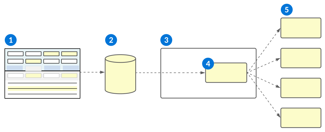
| An event definition is configured that specifies:
|
|---|---|
| An event rule and external event target definition subscribe to the event definition that specifies:
|
| Your external AWS EventBridge account. |
| The refined payload is sent to the AWS Event Bus specified in the event rules and event external target definition. |
 | Subscribers to the Event Bus receive the payload information. |
Event configuration
Configure events to notify external targets when business data changes occur with the Event Definitions, Event External Target Definitions, Event Rules, and Event Status Inquiry applications.
Configure different parts of the event in the following applications:
- Event Definitions application—Define the criteria to initiate the event.
- Event External Target Definitions application—Define any external targets for the event payload. If your event definition is only being sent to internal targets, no configuration is needed in this application.
- Event Rules application—Receive event definition payloads, filter the results, and route them to the appropriate targets.
- Event Status Inquiry application—Review the status of emitted events, errors, and resubmit any event failures once the issue has been resolved. System administrators are also able to view payload content.
- Event Target Delivery Status application—Review the status of targets queued from an event.
- Logic Block Builder—Configure the logic block to initiate the event if the event definition type is a User-Defined Event.
Prerequisites
For external EventBridge targets, you must configure your AWS account to allow Nextworld to send events. Contact support for help with implementation.
Event Definitions
In the Event Definitions application, you must:
- Create a new record and provide it with a unique name. This name is referenced in the Event Rules application.
- Select the Event Type. This determines what type of business process initiates the event, such as:
Workflow State Change—The event initiates when a record's workflow state is changed.- Define the Workflow To State and Workflow To State Type for the event.
- Optionally, select a Workflow Type to further refine the type of record which can initiate the event.
User-Defined Event—The event initiates from a user defined event, such as a logic block. If a logic block queues a user-defined event then later throws an error, the whole logic block, including the event, is rolled back. Any record updates aren’t committed and the event isn't initiated.
- Add an Event Definition detail for each source table you want included in the payload. For workflow state change event types built over a Standard table you may only include a single entry. For Header Details, you can include an entry for both the Header and the Detail if the Detail table is the driving table of the event. For user-defined event types, you may have up to five payloads configured.
- Provide a unique name for each detail in the Payload Key field. This name is referenced in the Event Rules application.
- Open the detail to select the fields from your driving table which you want included in the payload.
Event External Target Definitions
If your event definition is using an EventBridge as an external target, there are additional steps that must be completed in the target AWS account. Learn more in AWS EventBridge configuration.
Then, in the Event External Target Definitions application, you must:
- Create a new record for each external target you want the event payload sent to, and provide it with a unique name. This name is referenced in the Event Rules application.
- Enter the type of target, and the Id used to identify where the payload information should be sent. For EventBridge targets, the value is the Amazon Resource Name (ARN) of the EventBridge Bus in the external AWS account which you want the events routed to.
- In the Role field, enter the IAM Role from the target AWS account.
Event Rules
In the Event Rules application, you must:
- Create a new record, and reference the event definition name. Some fields are automatically populated from the definition.
- Optionally, add filters to refine the records from the definition source tables which are included in the payload.
- Reference the Payload Key for the source table which you want to filter.
- For events of type
Workflow State Change, you can also add Workflow From State, Workflow From State Type, or a Workflow Type if it has not previously been defined on the definition.
- In the Targets subtable, create an entry for each target you want the payload sent to.
- Provide each target with a unique name. This name is referenced in the Event Target Status Inquiry application when reviewing event statuses and errors.
- If the target is an external target, provide the unique name of the event external target definition you configured.
- If the target is a logic block, in the EventRuleTargets.LogicBlockInputOutputName field, enter the unique name of the data source in the logic block's Input and outputs subtable. The logic block must be either a Transaction or Background Task type logic block, and it can only have one input/output specified in the Inputs and outputs subtable.
- Select the Active checkbox and save the record to activate your event rules.
Logic Block Builder
If your event type is User-Defined Event and will be initiated by a logic block, in the Logic Block Builder, you must:
- Open the appropriate logic block and select the Queue Event action.
- In the Event Name field, reference the name of the event definition.
- Map any additional payload entries.
Event Status Inquiry
In the Event Status Inquiry application, filter the list for your event definition and review the status. Events with a status of Delivered were successfully emitted and routed to their targets, and no further action is needed.
Other statuses indicate the event has not been successful, and may require review, such as:
Warning—The event did not reach one or more of the targets defined in the Event Rules application. Open the detail form of the record and review the Event Targets for more information.Error—The event errored when it tried to initiate. Open the detail form of the record and review the Emission Error(s) field for more information.
Once any issues have been resolved, select the Resubmit Event form action in the detail of the record.
AWS EventBridge configuration
Configure an AWS EventBridge as an external event target for your events.
In the target AWS account, you must:
- Create a new EventBridge Event Bus.
- Copy the Event bus ARN.
- Create an IAM role that grants access to the action
events:PutEvents. This role is assumed by Nextworld in order to publish an Event on your Event Bus.- Add a Trust Relationship to the role to enable Nextworld to assume the role.
- Contact the Nextworld Cloud Operations team to get the Nextworld account number.
Event Definitions application
Application developers use the Event Definitions application to define the criteria to initiate events.
Event definitions are part of a multistep configuration. Learn more in Event configuration.
Criteria for an event definition include:
- The type of event, such as a workflow state change or user-defined event, which initiates the event process.
- The fields from the underlying table which should be included in the event payload.
Select the Add Event Definitions Detail button to create a payload entry. The Payload Key field is a unique name which is used to identify the payload entries in the Event Rules application. If the driving table is the Detail table of a Header Detail, you can optionally include an entry for the Header table if you want header fields included in the payload.
Use the Edit row action to open the detail for each entry. Define which fields should be included in the payload.
Workflow State Change
For Workflow State Change event types, you must define the Workflow To State and Workflow To State Type which a record must reach to initiate the event. Optionally, select a Workflow Type to limit the event definition to only a certain type of record.
Event External Target Definitions application
Application developers use the Event External Target Definitions application to define the target type and unique identification for external targets of event payloads.
Event external target definitions are part of a multistep configuration. Learn more in Event configuration.
Create a record for each external target you want event payloads sent to. The unique name of the record is used in the Event Rules application to link the definition, rules, and external target.
Specify the Id. For example, with a target type of EventBridge, you must specify the Amazon Resource Name (ARN) of the EventBridge Bus which you want events routed to when the target is invoked.
Event Target Delivery Status Inquiry application
Application developers use the Event Target Delivery Status Inquiry application to track details of event target delivery, including their type, status, and emitting user.
Select the Bulk Resubmit Event to Targets form action to initiate a bulk resubmission of all failed event to their specified targets.
Event Rules application
Application developers use the Event Rules application to receive event payloads defined in the Event Definitions application, filter the results, and route them to the appropriate targets.
Event rules are part of a multistep configuration. Learn more in Event configuration.
General
Create a new event rule record for each event definition you define. Enter the name of your event definition to pull in details from the definition record.
Filters
Optionally, apply numeric value filters to fields from the source table to limit the type of records which can initiate the event. For example, if you only wanted records included from the Sales Order detail table which have a Requested Quantity of more than 10, that fall within the date range of January 01, 2023 and June 30, 2023, you could configure the Filters subtable with:
| Payload Key | Field | Operator | Value |
|---|---|---|---|
| SalesOrderDetail | RequestedQuantity | Greater Than | 10.00 |
| SalesOrderDetail | RequestedDate | Greater Than | 12/31/22 |
| SalesOrderDetail | RequestedDate | Less Than | 07/01/23 |
For definitions of type Workflow State Change, you can also select a Workflow From State, Workflow From State Type, or Workflow Type which the record must match in order for the event to be routed to the provided targets.
Targets
Configure the targets which should receive the event payload when events match the filter criteria defined in the filters. Targets can be of type External or Logic Block.
For targets of type External, you must include the EventRuleTargets.EventRuleExternalTarget for a target defined in the Event External Target Definitions application.
For targets of type Logic Block, you must enter the name of the data source from the logic block's Input and outputs subtable in the Logic Block Input/Output Name field.
If your target is a logic block built over a Header Detail structure, there are additional configuration options required. Learn more in Event configuration.
Event Status Inquiry application
Application developers use the Event Status Inquiry application to track details of emitted events, including their status, payload content, target, and errors.
Events are part of a multistep configuration. Learn more in Event configuration.
Filter the list form for your event definition. Events with a status of Warning indicate that the event did not reach one or more of the targets defined in the Event Rules and Event External Target Definitions application. Events with a status of Error indicate there was an error when the event was initiated.
Select the Bulk Reroute Failed Events form action to initiate a bulk resubmission of all failed events.
Open the detail form of an event record to review information on event failures. Once issues have been resolved, select the Resubmit Event form action to resubmit that specific event.
Connectors
Connectors facilitate communication between external systems and Nextworld. You can use them to send and receive data, or to initiate logic in an external system, such as J.D. Edwards.
Like endpoints, connectors send and receive data between systems. Unlike Nextworld endpoints which require configuration of the request and response bodies, connectors have a user-friendly interface that allow you to use data mappings to select and filter for the fields and business data you want included. Connectors currently support several registrations, including:
- Batch data sync—Schedule or manually initiate a data sync which imports a copy of data from an external system, and imports it into a platform table. This data can then be manipulated or used in other processes.
- Real-Time data—View data from an external system in real-time within a platform application. This data is not saved or persisted in the platform.
- Logic invocation—Send business data and initiate a logic invocation within an external system.
Data sync
Use Batch Data Sync registrations to map external business data into an internal platform table. For example, you could configure a Batch Data Sync registration that imports data once a day from a J.D. Edwards financials table into an internal financials table. Then, you could build an interactive report over that data to view current financials data from the external platform.
Create a new table, or use an existing table, when you configure your data source registration. After you select an external table and populate the fields, select which fields you want included in your data sync, then map those fields to existing data items in your internal table. Or, if you created a new table, enter new data item names to create the appropriate data items while you map the fields.
After you create a data source registration in the connector configuration management record, another record is created in the Data Import Definitions application.
Data syncs can be manually run, or you can create a schedule for recurrent syncs to occur.
Real-time data
Use Real-Time Data registrations to show real-time external business data within an internal platform application. Real-time data is read-only and not stored or persisted in the underlying table. For example, you could configure a Real-Time Data registration to show business data subjected to compliance regulations which don't allow you to export business data.
You can create a Real-Time registration over an external orchestration, or a data service. If you create a registration over an external orchestration, you are registering a logic invocation from the external system to an internal platform table. Data service registrations are registering an external table to an internal table.
When you create your registration, the system also creates a new table to hold the incoming data. If you ever delete the registration, the table is also removed. After you select an external table and populate the fields, select which fields you want included, then map those fields to internal data items you want included in your table. If there are no existing data items for the external fields, you need to create them in the Data Item Definitions application.
Build an application over the internal platform table associated with the registration to view the real-time data.
Initiate logic
Use logic registrations to initiate logic in external systems, then map data from those external systems back into a logic block within the platform. For example, you could configure a logic registration that sends AR Invoice data into the J.D. Edwards platform. When the data is sent, a logic orchestration is called within their platform to insert that data into one of their tables. After the data has been assigned to their table and fields, they send an output back to Nextworld with the document number where our invoice data was recorded.
Select a registration type then load the available logic from the external system. When you name the logic registration and save the record, a logic block, input, and output table are automatically created to hold the external data.
After the logic is created, you can open the detail of that record to review and configure the input and output mappings between the external and internal systems. The external system fields are automatically available within the input and output mappings of the detail, but you must map internal fields to those external fields. When you select internal field names in the subtables, they are automatically added to the underlying table.
In addition to the outputs specific to the external system, all Logic Registration logic blocks have a generic Value output included with them called LogicInvocationSuccess. This value provides an overall success or failure indication at runtime, and can be used in conjunction with the logic block's message list in order to pivot the calling logic based on whether the external system's logic succeeded.
Connector applications
There are multiple applications used for connector configuration, including:
- Connector Catalog application—Review the external systems which you can connect to, as well as the supported versions. Catalog records are controlled and shipped by the platform. Learn more in Connector Catalog application.
- Connector Credentials Setup application—Configure the authorization type, connection URL, and credentials for the system you want to connect with. Connector credential records are created by system administrators in their development environments. Learn more in Connector Credentials Setup application.
- Connector Configuration Management application—Configure the details of the connector, such as the data mappings and schedule for the data sync. Reference the connector catalog record and connector credentials, then configure the data source registration or logic registration. Connector management records are created by system administrators in their development environments. Learn more in Connector Configuration Management application.
- Connector Sync Inquiry application—Review the status of any syncs which have been attempted for connectors. You can also view sync status records and summary information on the Connectors dashboard. Learn more in Connector Sync Inquiry application and Review connector sync statuses with the Connectors dashboard.
Learn more in Connector configuration overview.
Gateway Appliance
The Gateway Appliance securely connects the cloud-based enterprise application platform to on-premise assets located behind your company's firewall. The secure connection enables you to access on-premise resources from the enterprise application platform without directly exposing ports on your on-premise assets.
On-premise assets, such as servers and printers, configured behind your firewall are not connected to the cloud. While configuring these assets behind a firewall ensures your network remains secure, the firewall prevents installations, updates, and data transfers with cloud-based applications to the on-premise assets. The EAP Gateway Appliance connection gives your on-site assets secure access to the cloud.
Currently, the Gateway Appliance connects to the on-premise assets:
- JD Edwards World database (read-only)
- EPP configured label printers
Once installed and configured, the appliance gives you the ability to:
- Connect to local printers and route print jobs.
- Configure database connectivity and perform data synchronization between cloud-based applications and your on-site database.
- Upgrade and manage versions of the Gateway Appliance.
Security is provided for the appliance by an integration user account with a specified password.
Gateway Appliance installation
To install the Gateway Appliance, you must ensure your firewall and device requirements are met, install the appliance, then configure and connect your on-premise assets to the platform.
To see minimum requirements for hardware, operating systems, and software installations, see Gateway Appliance minimum technical requirements.
Firewall requirements
Ensure your firewall system settings allow the Gateway Appliance to:
- Have internet access to particular domains.
- Use HTTPS and WebSocket (WSS) protocols to send requests to and receive responses from the Nextworld Cloud on port 443.
Device requirements
Note the following default ports used during the installation process:
- Gateway Appliance: 8080
- JDE-World Pluggable Service: 8081
- Printing Pluggable Service: 8082
- EPP Configuration: 9082
User requirements
In addition to the default ports, the Gateway Appliance requires you to create an integration user in Nextworld that represents the appliance in all requests. The integration user can be the account for a designated employee, or it can be a dummy account you set up specifically for connection purposes. In the Users application, you must add the following two roles to the user record:
SYS - Base UserSYS - Integration Security Administrator
Other roles may also be applied to the user record. In addition to the roles, ensure that Multi-Factor Authentication is disabled for the integration user account.
Gateway Appliance Management application
In Nextworld, create a record for your gateway appliance. In the Gateway Appliance Management application, you must:
- Create a new record for the appliance.
- Populate the Services subtable with the services this appliance uses.
- Optionally, select the environments that can send requests to the appliance. If no environments are selected, the appliance can only connect to the default environment for the appliance user.
Gateway Appliance installation process
To install the gateway appliance, you must:
- Ensure your integration user account and firewall are established according to the instructions above.
- Log in to support.nextworld.net and search for "Gateway Appliance," then open the appropriate support article and download the appliance executable file.
- Navigate to the executable and open the installer tool.
- Follow the steps in the installation tool. Many of the fields are populated by default, however, you must supply the following values:
- User Id and Password: These values are from the integration user you created in Nextworld.
- JD Edwards World Configuration fields: Find these values in the JDE system setup.
- EPP Configuration > Host: Find this values in your EPP system setup.
Post-Installation information
In the Windows operating system, the Gateway Appliance installs to the C:\Program Files\gateway folder by default. In the Linux system, the Gateway Appliance installs to the /opt/GatewayAppliance folder by default. On both systems, this folder contains useful subfolders and files for any post-installation troubleshooting you need to perform:
- Access the
logsfolder to check the gateway appliance's event records when troubleshooting. - Open the
appliancefolder and access theapplication.propertiesfile to change any configurations after installing the gateway appliance, such as the integration user account or the service port and host information.- The
jdeworldandprintingfolders also haveapplication.propertiesfiles in their respectiveconfigsubfolders if you need to adjust configurations directly to those connected assets after you have completed your initial installation.
- The
Additional platform configurations
If your Gateway Appliance is being used in a connector, you must register your data source to complete the connection. Learn more in Connector configuration overview.
If your Gateway Appliance is being used for EPP printing, you must:
- Add a record for your onsite printers in the Printer Definitions application.
- Add a logic block, or add to an existing logic block, that inserts a record with all of the required information into the
WriteEPPPrintRequeststable. There is a table trigger configured on this table that routes the information to the gateway appliance.
Gateway Appliance minimum technical requirements
Because your on-premise assets process your data, certain minimum requirements must be in place for the Gateway Appliance to function correctly. Your hardware, operating systems, and software installations must meet or exceed the following standards.
Hardware
| Category | Minimum requirement |
|---|---|
| Processors |
|
| Memory |
|
| Hard drive |
|
Operating systems
| System | Supported versions |
|---|---|
| Linux | |
| Windows |
|
Software
| Software name | Supported versions |
|---|---|
| Postgres | |
| Java |
|
Gateway Appliance Management application
System administrators use the Gateway Appliance Management application to define the services between the Gateway Appliance and the platform.
Services the Gateway Appliance can have enabled include:
- Connecting to local printers and routing print jobs.
- Data synchronization between the platform and your on-site database.
Once you select the services you want enabled, you can optionally:
- Define the environments which the appliance connects to. If no environments are selected, the connector only applies to the appliance user's default environment.
- Modify the behavior of the Gateway Appliance using the Configuration Properties subtable. For example, you could create a configuration property that specifies the frequency that a pluggable service runs health checks.
Once a record is created in the Gateway Appliance Management application, you reference it a connector configuration. Learn more in Connector configuration overview.
Gateway Appliance Message History application
System administrators use the Gateway Appliance Message History application to review messages passed between the appliance and Nextworld.
Records include information such as number of attempts and delivery status for each message. This application is useful for debugging.
Gateway Appliance Service Catalog application
System administrators use the Gateway Appliance Service Catalog application to review the services available for their appliances.
Add services to records in the Gateway Appliance Management application to enable them. Then, reference that management record in the Connector Configuration Management application.
Learn more in Connector configuration overview.
Printer Definition application
System administrators use the Printer Definitions application to register their onsite printers for use with the Gateway Appliance.
Add the printer name, description, and site, then reference the name of the gateway appliance that fulfills the printing requests.
Connector configuration overview
System administrators configure connectors with the Connector Catalog, Connector Credential Setup, and Connector Configuration Management applications.
Connector Catalog
Use the Connector Catalog application to view the external systems which the platform can connect to. Learn more in Connector Catalog application.
In the Connector Catalog application, identify the record for the external system you want to connect with. The internal record name is used in the Connector Credentials and Connector Management applications.
Connector Credentials
Use the Connector Credential Setup application to specify the URL, authorization type, and authorization credentials for a connector. Learn more in Connector Credentials Setup application.
In the Connector Credentials application, you must:
- Create a new record.
- In the Credentials Name field, create a unique name. This name is referenced in the Connector Management record.
- In the Connector Name field, enter the internal name of the connector catalog record.
- Enter the URL and authorization type. If the authorization type requires additional information, fill in those fields.
- Optionally, enter an environment. If no environment is specified, the default environment from the external system's instance is used.
Connector Configuration Management
Use the Connector Configuration Management application to configure the specifications of their connection to external systems. Learn more in Connector Configuration Management application.
In the Connector Configuration Management application, you must:
- Create a new record and reference the connector catalog and connector credential records. If the external system is JDE World, also reference the gateway appliance record.
- Optionally, enter a default security group which ensures the metadata created by the connector is assigned to that security group.
- Configure your registration.
The configuration steps are different for each type of registration. View the following topics for more information:
Batch Data Sync registration configuration
Application developers configure batch data sync registrations within a Connector Configuration Management record to import data from an external system into a platform table.
Connector Configuration Management application
Inside your connector configuration management record, select the Register Batch Data Sync form action, then:
- Select a Registration Type. You can either send data to an existing table, or create a new table. If you sync to a new table, the table record is created when you save.
- Select the table from the external system which you want to data sync with. If this is the first time you are configuring a connector with that system, or a new table has been added in the external system which you want to connect with, select the Refresh Table field action.
- If the connector is to JDE World, select the Fetch Table Mappings field action. This field action is only available for this connection type.
- Select the Populate Mappings field action to import all of the fields from the external system.
- In the data mappings, select the ConnectorExistingTableMappings.ConnectorDataMappingIsSelected checkbox on any fields which should be included.
- Enter a ConnectorExistingTableMappings.DataImportMappingTableSchemaField for the included fields. If you are importing into a newly created table, you can either select an existing ConnectorExistingTableMappings.DataImportMappingTableSchemaField or create a new data item by entering a value into the ConnectorNewTableMappings.ConnectorFieldMappingNewDIName field. If a value is entered into the ConnectorExistingTableMappings.DataImportMappingTableSchemaField, the ConnectorNewTableMappings.ConnectorFieldMappingNewDIName field is ignored.
- Optionally, use filters to refine which records are included in the data sync. The filters are built over the internal table the data is being imported into, but are applied to the external table's data at runtime. You can only use certain expressions, such as Equal, Not Equal, Greater Than, Greater Than or Equal, Less Than, or Less than or Equal.
- Select the type of data sync you want to configure in the Import Mode field. You can have the data sync run for Inserts, Updates, or both. If the data sync runs for updates, select the match fields which you want included.
- Optionally, select the Enable Net Change checkbox. This ensures better performance for data syncs by only retrieving records that have been inserted or updated since the last sync. If selected, provide a field or fields that contain modified date information. For example, JD Edwards stores their date and time in separate fields, so you would select the date as the primary field and the time as the secondary field.
- In the Data Sync Interval field, select how often you want the data sync to occur. This can be once, recurring, or manual.
Once you save, a data import definition record is automatically created with your data mappings. On the Batch Data Sync page, you can view the data sync registration record you just configured, and:
- Select the Edit row action on the record to access additional scheduling options for your data sync, such as the recurrence rules, start date, and end date.
- Select the Edit Data Mappings row action to open the data import definition record where you can edit and update the mappings.
- Select the Execute Data Sync row action to manually execute the data sync.
Review the status of data syncs in the Data Sync Inquiry application, or on the Connectors dashboard page. Learn more in Connector Sync Inquiry application and Review connector sync statuses with the Connectors dashboard.
Logic Invocation registration configuration
Application developers configure logic invocation registrations within a Connector Configuration Management record to send business data and initiate a logic invocation within an external system.
Inside your connector configuration management record, select the Register Logic Invocation form action, then:
- Select your Logic Invocation Type. The types available are based on the connector catalog record you selected. For example, you may configure logic invocations of type
Orchestrationfor a J.D. Edwards connector. - Select the Reload External Listings form action to ensure you have the most current data from the external system.
- In the External Name field, select the external system invocation.
- In the New Logic Registration Name field, create a name for your invocation. Once saved, a logic block, input table, and output table are all created. The tables are work table which are used to pass input and output data between the external system and internal logic blocks.
- Save the record.
On the Logic Registration page, select the Edit row action on the detail record of your logic invocation, then:
- Review the name of your logic block, input table, and output table. The logic block cannot be updated or changed, but can be referenced by other logic blocks to use the imported data.
- In the Input Mappings and Output Mappings subtables, review the input mappings. The external system fields are automatically filled into the subtables, but you must map internal fields to those external fields. When you select internal field names in the subtables, they are automatically added to the underlying table.
Once created, logic blocks can call the logic registration by referencing the New Logic Registration Name. This is commonly done through use of a row or save action. For example, a transaction logic block could call the connector logic block, use Field Mappings to map data items from Nextworld into the J.D. Edwards invocation call, then map the output data from J.D. Edwards into an internal table.
Real-Time Data registration configuration
Application developers configure real-time data registrations within a Connector Configuration Management record to view data from an external system in real-time within a platform application. This data is not saved or persisted in the platform.
Real-Time Data registrations can be built over external data sources of type Orchestration or Data Service. If you create a registration over an external orchestration, you are registering a logic invocation from the external system to an internal platform table. Data service registrations connect an external table to an internal table.
Orchestration
Inside your connector configuration management record, select the Register Real-Time Data form action, then:
- If this is your first time creating a registration in this connector, or new external data sources have been added, select the Reload External Listings form action. This process runs in the background and sends a notification when it has completed.
- Select
Orchestrationin the External Data Source Type field. - Specify a name for the associated table the system creates for this registration. That table is automatically created in the same Product Family and Module as the connector configuration management record, and holds the real-time data as it comes in. To make changes to the fields, indexes, and other table options, edit the the configuration management record.
- Enter the name of the external orchestration and save the record.
On the Real-Time Data Registration page, select the Edit row action on your Orchestration record, then:
- Optionally, add a security group to secure the underlying table. Security is limited to RUID access.
- On the Field Mappings page, the input and output mappings are automatically populated for the external table.
- In the Output Mappings subtable, map the external grid to a platform subtable. Then, map any other fields you want included from the record.
- In the Subtable Output Mappings subtable, map each value you wanted included from the grid into a field within the platform subtable.
Once you save your registration, build an application of type Standard or Advanced List over the platform table associated with the registration. If the fields change in the external table, select the Refresh Resource row action on your registration and update the mappings.
Data Service
Inside your connector configuration management record, select the Register Real-Time Data form action, then:
- If this is your first time creating a registration in this connector, or new external data sources have been added, select the Reload External Listings form action.
- Select
Data Servicein the External Data Source Type field. - Enter the name of the external table, then select the Populate Mappings field action.
- In the Data Mappings subtable, select the ConnectorExistingTableMappings.ConnectorDataMappingIsSelected checkbox on any fields which should be included.
- Enter a ConnectorExistingTableMappings.DataImportMappingTableSchemaField for the included fields. If the data item you need does not exist, you must create it in the Data Item Definitions application.
Once you save your registration, build an application of type Standard or Advanced List over the platform table associated with the registration.
Route data changes back to the external system
To make changes to the external system's data, you must configure an action block over the real-time registration's internal table. An action block is automatically created and associated with the table once you save the registration. To configure, you must:
- In the connector configuration management record, navigate to the Real-Time Registration page and select the Edit row action on your registration record.
- Navigate to the Action Blocks page and select the Create Action Block field action.
- Select the type of action you want the logic block to perform, such as Insert, Update, or All. Once saved, the logic block is added to the Action Blocks subtable. You can either have an action block that performs ALL action types, or action blocks that perform individual actions.
- Select the View Action Block field action in the subtable to open the logic block, then:
- Delete the existing action.
- Configure the action block to call an external endpoint, or a logic block created in a Logic Registration within the same connector configuration management record. The processing logic block that the action block calls, or the Call External Endpoint action, must call an external API to perform the updates. You cannot configure the action block to directly make record changes.
- Do not change the action block's inputs or outputs. It can only be built over the registration table, and any other inputs or outputs added are ignored. To use additional inputs or outputs, add them to the processing logic block that this action block calls.
Connector Configuration Management application
System administrators use the Connector Configuration Management application to configure the specifications of their connection to external systems.
The Connector Configuration Management application is part of a large configuration process. Learn more in Connectors and Connector configuration overview
Reference the connector record from the Connector Catalog application which contains the correct external system information.
General Configuration page
Define the product module and product family. Optionally, define a default security group.
Enter the name of the credentials record from the Connector Credential Setup application which provides the URL, authorization type, and login credentials needed for the connector.
Batch Data Sync Registrations
Import data from the external system into a platform table.
Select the Register Batch Data Sync form action to open and configure your data sources. Once a data source has been saved, a record is created on the Batch Data Sync Registration page which you can view and edit. Select the Edit row action to open the details of the record. Navigate to the Scheduling page in the detail to configure the schedule for your data sync, such as the recurrence rules, start date, and end date.
Additionally, upon a save, a record is created in the Data Import Definitions application with your mappings and connector information. Select the Edit Data Mappings row action on the record to open the data import record. This allows you to edit or add additional field mappings to your registration.
Learn more in Batch Data Sync registration configuration.
Logic Registrations
Invoke business logic in an external system.
Select the Register Logic Invocation form action to open and configure your logic invocations. Once a logic invocation has been saved, you can select the Edit row action to create the input and output mappings. If the logic invocation has been updated on the external system, select the Refresh Resource form action.
Learn more in Logic Invocation registration configuration.
Real-Time Data Registrations
Show data from an external system within the platform in real-time.
Select the Register Real-Time Data form action to open and configure your data source. Once a real-time data registration has been mapped and saved, a record is created on the Real-Time Data Registration page which you can view and edit.
Learn more in Real-Time Data registration configuration.
Connector Catalog application
System administrators use the Connector Catalog application to view the external systems which the platform can connect to.
Each supported system has a record in the application. Reference the connector record name in the Connector Configuration Management application to configure your connector. Learn more in Connectors.
Currently, the platform allows you to connect to J.D. Edwards with orchestration logic invocation and to data sync.
General Configuration page
Review the supported versions, product family, and product module.
Connector Supported Logic Types page
Review the supported logic invocation types.
Learn more in Connectors and Connector configuration overview.
Connector Credentials Setup application
System administrators use the Connector Credential Setup application to specify the URL, authorization type, and authorization credentials for a connector.
To create a new connector credential, you must reference the name of an existing connector record from the Connector Catalog application. The connector catalog has a record for each external system which the platform can connect with. Then, you must specify the credentials needed for the system. For example, J.D. Edwards requires either a Username and Password, or SSO Authentication.
Optionally, specify an environment from within the external system. If no environment is selected, the default environment for the login credentials is used.
Once your connector credential record has been created, reference its unique key in the Connector Configuration Management application.
Learn more in Connectors and Connector configuration overview.
Connector Sync Inquiry application
System administrators use the Connector Sync Inquiry application to review the status of any syncs which have been attempted for connectors.
Each connector configured in the Connector Configuration Management application has a record in the application. Whenever a sync is attempted, whether manual or scheduled, the record is updated with the most recent information.
This application feeds data to the Connectors dashboard. Learn more in Review connector sync statuses with the Connectors dashboard.
Summary
Review the sync status, time of sync, and time of next sync scheduled sync.
Errors and Details
If the most recent sync failed, provides any internal platform errors related to the failure.
Learn more in Connectors and Connector configuration overview.
Data Sync Run Inquiry application
System administrators use the Data Sync Run Inquiry application to review records for data syncs which occurred as part of a connector.
Connectors facilitate communication between external systems and Nextworld. You can use them to send and receive data in a data sync.
Each record includes general information about the data sync, status of the run, and an attached CSV that includes all of the rows from the data sync. To view the CSV, select the Attachments form action.
Learn more in Connectors.
Review connector sync statuses with the Connectors dashboard
System administrators use the Connectors dashboard to monitor the status of sync attempts from configured connectors. For example, if an environment has a scheduled sync configured to send and retrieve data from J.D. Edwards, system administrators could use the Connectors dashboard to ensure each sync was successful, review the name of the table or logic block where the data is being held, and open up the details of a record to view any error messages.
Connectors send and receive data between the platform and an external system tables and logic blocks. Learn more in Connectors.
The Connectors dashboard is made up of the following dashboard cards:
- Recent Syncs by Data Source—Shows a summary view of data syncs based on the data source registration. The summary view provides the time of last attempted sync, status of the sync, and the name of the table being synced.
- Data Sync Execution—Shows records for every sync attempted by a connector. Each record provides the sync status, connector name, data import run number, and the name of the table being synced.
Webhooks
External systems send webhook notifications into Nextworld when events occur. This allows business logic within Nextworld to execute in response to those events.
Webhooks eliminate the need to poll external systems in order to stay informed about changes. Instead, the external system proactively sends a notification to your webhook at the time an event occurs. This enables Nextworld to react to that event immediately.
For example, you can be notified anytime an item is purchased in another system, and populate a Nextworld table with that information.
Learn more in the following topics:
- Webhook configuration
Configure webhooks using the Credential Management , Event Definitions , Webhook Definitions and Webhook Setup applications.
- Credential Management application
Use the Credential Management application to create and manage credentials for external systems, such as HMAC keys for webhooks OAuth for MCP servers, or PGP encryption for data imports and exports.
- Webhook Definitions application
Use the Webhook Definitions application to select the authentication type and event definition for your webhook. Then, configure the data mappings from a webhook request into your event.
- Webhook Setup application
Use the Webhook Setup application to configure environment-specific information for a webhook definition, such as the secret, lifecycle, and run as user. You also use it to generate the URL that you reference in the external system configuration, and to activate your webhook.
- Webhook Log Inquiry application
Use the Webhook Log Inquiry application to view the webhook requests coming into the system. Each record shows either a successful or unsuccessful webhook event.
Webhook configuration
Configure webhooks using the Credential Management, Event Definitions, Webhook Definitions and Webhook Setup applications.
Credential Management application
If your webhook uses basic auth, go to the next step of configuration. If your webhook uses HMAC authentication type, in the Credentials Management application, you must:
- Create a new record and select HMAC for your credential type.
- Select your version, then select the Generate Secret field action.
- Copy your credential management record name. This is referenced in the webhook setup record.
Event Definitions application
You must configure an event definition that receives the data when a webhook request is received. Create an event definition of type User-Defined. On the Mapping page of your event definition, configure how to pass data into that event. Learn more in Event configuration.
Webhook Definitions application
In the Webhook Definitions application, you must:
- Create a new record and reference the name of your event definition.
- On the General Configuration page, select your authentication type. Options include:
- HMAC—Create a secret key in the Credential Management application, then use the key in the Webhook Setup application and in the external system. The key authenticates each inbound request using the specified HMAC algorithm.
- Basic Auth—Each inbound webhook request contains a username and password which is used to authenticate the request.
- On the Mappings page, configure your data mappings. This can be manually done, or you can create advanced mappings with a logic block:
- Manual Mappings—Use the Data Mapper to manually map data from your request into your event definition. Select the request body or header and drag the arrow to the appropriate event payload. Select the line connecting the two data points to view or edit the properties.
- Logic Block—Optionally, you can do an advanced mapping by specifying a logic block of type Data Mapping. In that logic block, you must configure your mappings using Set Values actions. It should have one JSON Object data item as an input, and a record as the output with the table that the event definition payload is built over as the shape. Once you enter the logic block name, the input and output mappings are automatically populated in the subtables. Add the event payload key in the output mappings where you want to map the payload information.
Webhook Setup application
In the Webhook Setup application, you must:
- Create a new record and enter your webhook definition name.
- If your webhook definition uses HMAC authentication, enter the name of your credential management record.
- Optionally, select the run as user and lifecycle.
- Save the record. This populates the URL which you reference in the external system.
Webhook Log Inquiry application
In the Webhook Log Inquiry application, you can view records for unsuccessful webhook requests. By default, only unsuccessful events are shown, but you can enable logging for successful events in the Webhook Setup record for the webhook definition.
To resolve an errored webhook, open the log record and review the error message. If your webhook was built with a data mapping logic block, you can debug the logic block to try and solve the problem. Once you have fixed the issue, use the Replay Request row action on the logging record to initiate the event again.
Open a record to see the webhook setup and definition record names, the timestamp, host, and the audit information for the request content such as the source IP address and request body.
Credential Management application
Use the Credential Management application to create and manage credentials for external systems, such as HMAC keys for webhooks OAuth for MCP servers, or PGP encryption for data imports and exports.
Different credential types have different requirements, such as:
- For webhooks, you must reference the key in the Webhook Setup application. Learn more in Webhook configuration.
- For MCP, the key is automatically included in the OAuth Provider application record. OAuth Provider and Credential Management records are automatically created with the same name as the MCP Definition record once it has been saved.
- For PGP encryption, you must:
- For data exports:
- Signing: Create an internal key record. Select the Generate button or paste an existing key in ASCII armored format. You'll use the internal private key to sign data exports. The platform uses the internal private key to sign exports. You provide the internal public key to the external system so it can verify the signature.
- Encryption: Create an external key record and paste the external system's public key in ASCII armored format. The platform uses the external public key to encrypt exports.
- For data imports:
- Signature Verification: Create an external PGP public key record and enter the external system's public key. This verifies the signature on incoming files. This is usually the same key used to encrypt outbound files going to the external system.
- Decryption: Create an internal key record. Select Generate or paste an existing key in ASCII armored format. The platform uses the internal private key to decrypt imports that are encrypted with the corresponding internal public key in the external system. This is usually the same key used to sign outbound files going to the external system.
- For data exports:
Webhook Definitions application
Use the Webhook Definitions application to select the authentication type and event definition for your webhook. Then, configure the data mappings from a webhook request into your event.
General Configuration page
Select the authentication type for your webhook. Options include:
- HMAC—Create a secret key in the Credential Management application, then use the key in the Webhook Setup application and in the external system. The key authenticates each inbound request using the specified HMAC algorithm.
- Basic Auth—Each inbound webhook request contains a username and password which is used to authenticate the request.
HMAC is the industry standard and requires a HTTP Header that your hashed secret value is stored in, and a hashing algorithm.
Mappings page
Use the visual data mapper to manually map data from your request into your event definition.
Optionally, you can do an advanced mapping by specifying a logic block of type . In that logic block, you must configure your mappings using Set Values actions. It should have one or more records as the outputs with the table(s) that the event definition payload is built over as the shape(s) Once you enter the logic block name, the input and output mappings are automatically populated in the subtables. Add the event payload key in the output mappings where you want to map the payload information.
Webhook Setup
View a read-only inline version of the Webhook Setup application. This shows all of the places where the webhook definition is active in your current environment. Select the Create action to navigate to the application where you can create new setup records.
Webhook Setup application
Use the Webhook Setup application to configure environment-specific information for a webhook definition, such as the secret, lifecycle, and run as user. You also use it to generate the URL that you reference in the external system configuration, and to activate your webhook.
Specify the webhook definition you want to configure. Then, save the record to populate an endpoint URL. The external system makes requests to this endpoint.
If the webhook definition uses an HMAC authentication type, enter the name of your credential management record.
Optionally, select a run in lifecycle. If none is selected, base is used by default.
Optionally, select the Log Successful Requests checkbox to enable logging of successful webhook calls. Logging errors is done by default. To view logs for your webhook, navigate to the Webhook Logging application. Learn more in Webhook Log Inquiry application.
Webhook Log Inquiry application
Use the Webhook Log Inquiry application to view the webhook requests coming into the system. Each record shows either a successful or unsuccessful webhook event.
By default, only unsuccessful events are shown, but you can enable logging for successful events in the Webhook Setup record for the webhook definition. To resolve an errored webhook, open the log record and review the error message. If your webhook was built with a data mapping logic block, you can debug the logic block to try and solve the problem. Once you have fixed the issue, use the Replay Request row action on the logging record to initiate the event again.
Open a record to see the webhook setup and definition record names, the timestamp, host, and the audit information for the request content such as the source IP address and request body.
Model Context Protocol (MCP)
Model Context Protocol (MCP) is an open protocol standard for AI integrations. It enables you to build secure, standardized connections between organizational data and AI consumers, such as large language models (LLMs), without requiring custom integrations for each system.
MCP allows the LLM to access a company's data in real-time, ensuring it has up-to-date, system-specific information. MCP also allows:
- LLMs to take actions within systems, such as updating, creating, or executing operations.
- Multiple MCP compatible clients, such as Claude, Gemini, or ChatGPT to connect to a single MCP server without requiring custom integrations.
- MCP clients to access and perform actions in multiple systems through their MCP servers simultaneously.
Code Mode
Nextworld's implementation of MCP includes Code Mode, which extends these capabilities further. Code Mode enables the server to write and execute its own code at runtime, and provides many features for the server, including:
- Precise, accurate results—Answer any question, no matter how unique or specific, without requiring specific implementations or custom logic blocks for different industries and customers. Instead of reasoning over data or relying on pre-built tools, the server is able to write a script, run it server-side, and return an answer. Data operations run as code rather than LLM reasoning which greatly reduces miscounts and hallucinated results.
- No context window limitations—Data fetching, filtering, and aggregation run as executed code on the server. This means large record sets can be operated on without the LLM losing track.
- Eliminates custom implementations—Requirements that previously required platform development or custom logic blocks can be resolved by exposing the MCP server which only takes minutes to set up.
Code Mode combines the LLM's full coding capabilities with native platform tools, like calling external endpoints or fetching table records, to answer questions no pre-built logic block could anticipate.
MCP protocol components
MCP has multiple components, as seen in the diagram below:
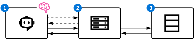
| Object | Example | |
|---|---|---|
| MCP Client—The application or interface that orchestrates interactions between the AI model and MCP servers. MCP clients are often chatbots, such as Ed for Nextworld and Claude for Anthropic. The client:
| You connect Claude to the Nextworld MCP server and grant him access to the Work Orders application. Claude requests the tools and resources from the MCP server. Once received, the client routes them to the model. You can ask Claude to perform any actions which the server and your internal platform permissions allow. |
| MCP Server—The MCP server which serves as the intermediary between the MCP client and a system. Servers are typically built by the system owner or a third-party developer and provide tools and resources for the AI model. Tools are functions or actions that the AI model can invoke to perform operations in the connected system. Resources provide contextual data and information for the LLM to read and understand. The MCP server:
| Nextworld MCP server notifies the client that RUID actions and workflow transitions can be performed on the application's records. |
| The system which the LLM accesses. | Prompts entered into Claude make changes to the WorkOrders table. |
Nextworld uses MCP in several ways:
- Connecting an external MCP client to the platform—Exposes platform data and allows you to access, analyze, and perform actions on an application's data and logic blocks from within an an MCP client, such as Claude or ChatGPT. Learn more in Connect an external MCP client to the platform.
- Connecting Ed to an external MCP server—Allows Ed to leverage an external system's MCP server's tools and resources to perform actions and get information. Learn more in Connect Ed to external MCP servers.
- Connect Ed to Nextworld's MCP server—Allows Ed to leverage Nextworld's MCP server's tools and resources to perform tasks and answer questions about applications and platform features. Learn more in Connect Ed to Nextworld's MCP server.
Connect Ed to Nextworld's MCP server
Connect Ed to Nextworld's MCP server to give him access to platform data and objects. The MCP servers act as the intermediary between Ed, the MCP client, and the objects he interacts with.
Nextworld's MCP server allows you to read, insert, update, delete, and create records, or transition a record's workflow. For example, you could connect Ed to the Sales Order application. Then, from any location within the platform, you couple open Ed and enter prompts to retrieve, analyze, update, create, or delete sales orders.
You can connect to a single application or project, or to a bundle of metadata objects which includes tables and logic blocks.
Configuration
To enable Ed to connect with the platform's MCP server, you must:
- Either open the application or project you want to connect with, or navigate to the MCP Bundle application.
- If you are creating an MCP Bundle, create a new record then add each object you want included on the Metadata Objects page.
- Open the MCP Agent Option action menu next to the record name.
- Select the
 Create MCP Agent button. This automatically creates the Agent Toolset Builder and Agent Builder record required for connection.
 - In the agent record, the parent agent for your agent must either be Ed, or another agent that is within the Ed hierarchy. Modify the Agent Persona and Agent Prompt as needed.
Connect Ed to external MCP servers
Application Developers use the External MCP Definitions application to enable Ed to connect to external MCP servers.
Ed manages the conversation and determines when to use external capabilities, while the MCP server provides the tools and resources that define what actions Ed can perform within the connected systems. Learn more in Model Context Protocol (MCP).
When Ed connects to an external MCP server it grants him access to the external system's data. For example, you could connect Ed to the:
- Google Maps MCP server to grant him access to geospatial data, such as weather forecasts and routing details, from the Google Maps platform.
- FreshDesk MCP server to integrate him into managing, creating, and closing your support desk tickets.
- SalesForce MCP server to read, query (SOQL), and analyze live Salesforce CRM data.
Ed can also connect to Nextworld's MCP server to enable him to access and update platform data. Learn more in Connect Ed to Nextworld's MCP server.
Configuration
To connect Ed to an external MCP Server, you must:
- In the External MCP Definitions application, create a record for each MCP server.
- In the Agent Toolset Builder application, create a record and select
MCP Toolsfor the Toolset Type. Then, reference the name of your MCP Definition record. - In the Agent Builder application, configure your agent. The parent agent for your agent must either be Ed, or another agent that is within the Ed hierarchy.
Ed has a network of agents he is delivered with, but also accesses any additional agents added to his network in his current environment. Learn more in Agents.
Enable Ed to connect to external MCP servers within your environment
System administrators use the External MCP Definitions application to configure connections between Ed and external MCP servers. External MCP Definitions are delivered but require additional configuration steps within your environment.
Ed can also connect to Nextworld's MCP server to enable him to perform actions on platform applications and objects. Learn more in Connect Ed to Nextworld's MCP server.
Learn more about MCP in Model Context Protocol (MCP).
External MCP Definitions application
In the External MCP Definitions application, find the record for the MCP server you want to connect Ed with. Open the record and navigate to the Setup page, then:
- Select the Authorization Type. The MCP server documentation provides this information.
- If you are connecting to an internal application, select
Nextworld MCP Server.
- If you are connecting to an internal application, select
- For external MCP servers, enter the URL from the MCP server. You can find this in the MCP server documentation for that system. For example, you could search for Github MCP server documentation. For the Nextworld MCP server, you do not need to populate a URL.
- If the MCP server requires OAuth 2.1, OAuth Provider records and Credential Management records are automatically created with the same name as the MCP Definition record when saved. Some servers have dynamic client registration and automatically populate the required fields once you enter the MCP Server URL. If not, you can find the Client Secret and Client ID in the MCP server documentation. Once configured, users are required to complete the authorization process when they prompt Ed to perform an action with the server.
MCP Setup application
System administrators use the MCP Setup application to configure MCP definitions. The MCP Setup application is an inline application available within the External MCP Definitions application, but can also be accessed from the Navigation Menu.
You can open the MCP Setup application from the Navigation Menu or by navigating to the Setup page within an External MCP Definition. The Setup record provides the URL and authorization information for an MCP definition. Learn more in Enable Ed to connect to external MCP servers within your environment.
OAuth Provider application
System administrators use the OAuth Provider application to configure OAuth 2.1 protocols to authenticate MCP server connections.
OAuth authorizations enables a third-party application to access an MCP server on our behalf by initiating an authentication interaction between our platform and the server, or by obtaining access itself. OAuth separates the MCP client, Ed, from the MCP server it is interacting with. The client, in this case Nextworld, is issued an access token by the third-party application that indicates the scope of access and allotted time to access the servers information.
Access the OAuth Provider application from the Navigation Menu, or from View OAuth Provider Configuration field action in the External MCP Definitions application. Fill in the required fields with information you receive from the MCP server's documentation. OAuth Provider records and Credential Management records are automatically created when you save the Setup portion of the MCP Definition record. If you need to change the client secret value, you must navigate to the Credential Management application and find the associated record.
Learn more about MCP server configuration in the Enable Ed to connect to external MCP servers within your environment topic.
Connect an external MCP client to the platform
Connect external MCP clients, such as Claude or ChatGPT, to the platform's MCP server. This enables the MCP client to access applications, projects, or bundles of objects to perform actions in the platform on your behalf.
The server dictates what actions MCP clients can perform within the platform. Nextworld's MCP server allows you to read, insert, update, delete, and create records, or transition a record's workflow. Learn more in Model Context Protocol (MCP).
You can connect external MCP clients to:
- An application—Connect to an individual application.
- A project—Connect to a project, including all of its public artifacts.
- A bundle—Connect to a specified group of tables and logic blocks.
Once connected, the MCP client retains access and can interact with the platform across multiple conversations.
How to connect
To connect an external MCP client, you must:
- Either open the application you want to connect with or navigate to the MCP Bundle application and open the record.
- Select the Get MCP URL
 button next to the application or record name. If you don't see the button, open the User Menu, navigate to the Ed page, and toggle on Show MCP Connection Option.
 - Copy the URL.
- Navigate to the external client and add a custom connector with your MCP URL link.
- Ask the MCP client to perform an action in the application. If you aren't sure what actions are permitted, ask the client.
You can also connect Ed to Nextworld applications. Learn more in Connect Ed to external MCP servers.
OAuth for Claude Enterprise
Claude Enterprise accounts can configure OAuth for connecting Claude to the Nextworld MCP server. This requires users to provide their own Personal Access Keys when using the MCP client to connect to internal applications. Without OAuth configured, the user who configured the MCP connection is listed on each action the client performs in the platform.
To configure, system administrators must:
- In Claude, open Settings and navigate to the Connectors tab. Select Add a custom connector.
- Name it, then paste the MCP URL link from the application, bundle, or project you are connecting with into the Remote MCP server URL field.
- Delete the API portion of the URL. For example, the Journal Entries application URL link is formatted like this:
https://apps.nextworld.net/ai/mcp?app=JournalEntry&apikey=d9ed5d49-14c5-4c2d-bd13-10fd21far059. In the field, you would usehttps://apps.nextworld.net/ai/mcp?app=JournalEntry - Expand Advanced Settings.
- In the OAuth Client ID field, enter your tenant ID.
- Select
Add. - Select the Connect button next to your Connector record.
When users sign in, they will be required to provide their Personal Access Key retrieved from the Settings page of their User Menu.
External MCP Definitions application
Application Developers and system administrators use the External MCP Definitions application to enable Ed to connect to external MCP servers. Ed can connect to external servers to leverage other system's tools and data.
Once your MCP Definition has been configured, there are additional configuration steps in the Agent Toolset Builder and Agent Builder applications. Learn more in Connect Ed to external MCP servers.
Ed can also connect with Nextworld's MCP server to connect directly with individual applications, or with bundles of objects. Learn more in Connect Ed to Nextworld's MCP server.
General page
Select your product family and module.
Setup page
System administrators use this page to enter the MCP Server URL and authorization information required for connecting to external MCP servers.
If your MCP requires authorization, an OAuth Provider and Credential Management record are automatically created with the same name as the MCP Definition when you save the Setup portion of the MCP Definition record. If you need to change the client secret value, you must navigate to the Credential Management application and find the associated record. Learn more in Enable Ed to connect to external MCP servers within your environment.
Once both components of the MCP definition have been configured, users within that environment can access the MCP server capabilities by typing prompts into Ed.
MCP Bundle application
Application developers use the MCP Bundle application to create groups of objects which both Ed and external MCP Clients can connect with.
General Configuration page
Select your product family and module.
Metadata Objects page
Enter each object you want the MCP server to have access to. Bundles support both tables and logic blocks.
Environment overrides
Use environment overrides to override previously configured values in a specific environment. Environment overrides are used for data imports, data exports, endpoint definitions, and event definitions.
Override definitions are environment specific, and can only be configured on certain fields. Overrides work by applying new values when a definition is called in the specified environment. This enables you to develop and test integrations without having to change values in the original definition.
For example, event definitions specify an Id where event payload information should be sent. If you configure an event to send payload information to an Eventbridge, you would not want to send test data to the Event Bus which has external subscribers. To test your event definition, you can create an environment override definition with an alternate Id. This allows you to test that the configuration works properly without sending test data to the business account which is specified in the original definition. Learn more in Event configuration and Event External Target Definitions application.
Or, you could replace the URL and endpoint secret from an endpoint definition to test the configuration without having to send a real request to the endpoint. Learn more in Endpoint Secret Setup application.
Once an environment override definition is configured, you must assign it to an environment in the Environment Override Assignment Setup application.
Learn more in:
- Environment override configuration
Configure an environment override with the Environment Override Definition and Environment Override Assignment Setup applications. Environment overrides enable you to create environment specific field value replacements for exports, endpoints, and event definitions.
- Environment Override Definitions application
Use the Environment Override Definitions application to define values to override previously configured values in data imports, data exports, endpoint definitions, and event definitions when in a specific environment.
- Environment Override Assignment Setup application
Use the Environment Override Assignment Setup application to assign an environment to an environment override definition.
- Environment Override Definitions application
Environment override configuration
Configure an environment override with the Environment Override Definition and Environment Override Assignment Setup applications. Environment overrides enable you to create environment specific field value replacements for exports, endpoints, and event definitions.
Environment Override Definitions
In the Environment Override Definitions application, you must create a new record and select the Add Environment Override Config Detail button to add an entry for each record you want to override. For each record:
- Select the appropriate override table. Valid tables are:
EndpointConfigDataImportTemplatesDataExportDefinitionExternalEventTargets
- Select the name of the record you want to create an override over. For example, the name of the endpoint definition.
- Select the Edit row action to open the detail detail.
- In the Overrides subtable, enter the name of the field you want to override, and provide the value you want in the field.
Environment Override Assignment Setup
In the Environment Override Assignment Setup application, you must create a new record. Enter the name of your override definition, and the name of the environment you want it applied in.
Environment Override Definitions application
Use the Environment Override Definitions application to define values to override previously configured values in data imports, data exports, endpoint definitions, and event definitions when in a specific environment.
Override definitions are environment specific, and can only be configured on certain fields. Overrides work by applying new values when a definition is called in the specified environment. This enables you to develop and test your integration definitions without having to change values in the original definition. Learn more in Environment overrides.
Select the Add Environment Override Config Detail button to add an entry for each record you want to override. For each record:
- Select the appropriate override table. Valid tables are:
EndpointConfigDataImportTemplatesDataExportDefinitionExternalEventTargets
- Select the name of the record you want to create an override over. For example, the name of an endpoint definition.
- Select the Edit row action to open the detail detail.
- In the Overrides subtable, enter the name of the field you want to override, and provide the value you want in the field.
Once an environment override definition is configured, you must assign it to an environment in the Environment Override Assignment Setup application. Learn more in Environment override configuration.
Environment Override Assignment Setup application
Use the Environment Override Assignment Setup application to assign an environment to an environment override definition.
Environment definitions are configured in the Environment Override Definitions application. Learn more in Environment override configuration.
Messages
Application developers, system administrators, and implementation teams configure the system to automatically send messages or notifications when message events are completed.
Define your message event parameters with logic blocks. Examples of events are received orders, processed payments, or completed manufacturing processes. One or more tables are referenced in every message event definition. This allows you to access records, such as directory information or business data, to use in the message templates.
The content created in the message template is sent to designated recipients when the event occurs. Messages can be sent to specific email addresses, contacts in the platform directory, or user groups. Define the recipients in the Group Definitions application, Logic Block Builder application, or in the message definition itself.
All of the configured components are brought together in a message definition. Message definitions are unique to each environment. Learn more in the following topics:
- Message events
System administrators and application developers use message events to execute actions, such as run a report or send a message, if specific criteria are met during a business process.
- Message templates
Use message templates in message definitions to create automated messages and notifications. Message templates contribute the content for messages.
- Message definitions
Message definitions hold references for message templates, message events, and associated configurations. Together, all of the configurations create automated messages and notifications.
- Message configuration
Configure messages to be sent to external and internal recipients with the Message Event Definition , Logic Block Builder , Message Template Setup , and Message Definitions applications.
Message events
System administrators and application developers use message events to execute actions, such as run a report or send a message, if specific criteria are met during a business process.
Message events tell the system to execute the actions subscribed to or associated with the event. For example, you might want to send an email message to a group of stakeholders when an important milestone is met in a business process, or when a manufacturing process is completed. For more information on how business events are used in message configuration, see the Message configuration topic.
Message events are part of a framework that includes:
- Emitter—This is the condition that executes a message event, and then tells the system that the event has occurred. Some examples of emitters are logic blocks, approval definitions, scheduled jobs, and workflow notification failures.
- Consumer—Detects emissions, then directs event actions that are subscribed to the message event.
- Action—What happens as a result of a message event. Actions are subscribed to message events.
For example, in the AP Payment Remittance application, the following message event framework is included:
- Emitter—A logic block that determines when a payment is processed and then executes an event action.
- Consumer—A message event tells the Nextworld system to execute the action that is subscribed to the event.
- Action—A message definition detects the broadcast, and then sends an email message to the supplier that contains information about the payment
Message Event Definition application
Application developers use the Message Event Definition application to define message events which execute actions if specific criteria are met in a business process.
In message events you can configure one or more payloads where you specify the table which you want to retrieve records from. Your payload can include addresses for your emails, or can be used to provide interpolated values for your message content. This allows a message to reference specific data items from the table.
To create a new message event, select the Add button in the Payload Entries section. Different fields are required based on what Shape Type you select.
Once you have created a message event, define the parameters of the event in the Logic Block Builder application.
See the Queue Event action topic for more information.
Message Event Status application
Application developers use the Message Event Status application to view the status and other information for message events that have been triggered.
A record is created in the Message Event Status application every time a message event runs. The record stores information about when the message event was executed, the status, payload information and the user that executed the event.
Message templates
Use message templates in message definitions to create automated messages and notifications. Message templates contribute the content for messages.
Message templates and message events are referenced together in the same message definition in order to configure messages. The business event also references a table. This allows message templates to interpolate data item values. This means that values found in the table can be referenced in the content of the template to provide business data.
You can create multiple messages definitions with their own message templates for the same event. This would send out different messages to various recipients when the event is executed. For example, if an order is placed in the system, the message sent to the warehouse and the message sent to the financials team would be different.
Learn more in the Message configuration topic.
Message Template Setup application
Application developers use the Message Template Setup application to create templates to use in recurrent messages, such as workflow notifications, approval messages, or emails.
Message templates are referenced in message definitions in order to provide the content. Message events are referenced in the same message definition to provide the parameters.
You can use values from tables referenced in the message event in the content of your message template. For example, you could reference a directory record to provide recipient information, or you could reference a date or time for when a business process was completed.
To include interpolated values from a table in your message content, use the format of:
{*PayloadEntriesName.DataItemName*}
Where:
- PayloadEntriesName is the name of the payload entry from the message event configuration. The Payload Entry subtable is where you reference a table in the message event.
- DataItemName is the name of the data item from the table that you want referenced in the message content.
If you do not specify the payload entry name, and only use {*dataitemname*} , the first payload entry in the subtable is defaulted.
To learn more about message definitions see Message definitions and Message Definitions application.
Message definitions
Message definitions hold references for message templates, message events, and associated configurations. Together, all of the configurations create automated messages and notifications.
Message definitions are unique to each environment. They may be defined by system administrators, application developers, or members of an implementation team.
A message is sent to designated recipients when a defined message event occurs. For example, a message may be sent to all stakeholders when a manufacturing or accounting process is completed.
The message content is created in message templates. Both the message event and message template are specified in the same message definition in order to send the correct message to the designated recipients when the event occurs.
For more information see Message Definitions application and Message configuration.
Message Definitions application
System administrators and application developers use the Message Definitions application to specify when to send a message, what message to send, and who to send the message to.
There are several considerations when you configure a message definition, such as:
- You must configure message event which defines the parameters for when the messages should be sent.
- You must configure a message template with the content of the message you want sent.
- The message event and message template(s) must be referenced in the same message definition. This allows the messages to be sent to the correct recipients when certain message events occur.
- Messages are only sent if the Active checkbox is selected.
- You can specify the recipients in the message definition, or with logic blocks or decision matrices.
Learn more in Message events, Message Template Setup application, and Message configuration topics.
Message configuration
Configure messages to be sent to external and internal recipients with the Message Event Definition, Logic Block Builder, Message Template Setup, and Message Definitions applications.
Configure messages with the following applications:
- Message Event Definition application—Specify the table which you want to retrieve records from. This can include addresses for your emails, or interpolated values for your message content.
- Logic Block Builder application—Create a logic block to queue the message event when the event is triggered. Optionally, map additional data sources to the event payload.
- Message Template Setup application—Define the content for the messages. Optionally, include interpolated values in your message content from the data source in your event payload.
- Message Definitions application—Define the message template, message event, and associated configuration. Together, they create the automated messages and notifications which the system sends to recipients.
There are also optional configurations for messages. These are configured in the following applications:
- Decision Builder application—Define conditional logic to determine which message template should be used.
- Group Definitions application—Define a predefined group that is specified as message recipients.
- Workflow Builder application—Define a workflow transition that prompts a message to be sent. To send messages for transitions, you must add a Post Run logic block to the transition that queues the message event to which your message definition is subscribed. To send notifications for workflow approval or rejections, you must configure an Approval Definition. See the Configure messages for workflow transitions, approvals, or rejections topic for more information.
Prerequisites
To send messages, your tenant must be configured with an email domain. See the Email domain setup topic for more information.
Message Event Definition
In the Message Event Definition application, create a message event and define the tables you want associated with your messages. Records from the tables can be referenced in the templates of your messages. See the Message events topic.
Logic Block Builder
In the Logic Block Builder application, you must create a Post Run logic block over the event that you want to queue the message, then:
- Select the Queue Event action.
- In the Details panel, in the Message Event field, enter the name of the message event you configured.
- If the business event must be executed in a certain order in relation to other events, use the Sequential Execution Key field to specify a key.
- Use the Payload Entries fields to map in values from a data source to the payload entry. These values can be used as interpolated values in the message content, or to provide recipients for the message.
Optionally, if you want a list of directory records to select your recipient from, you can also set up a logic block with the Build Directory Collection action. The logic block must not be a Background Task type logic block, since the logic block must run synchronously to provide the list of directory records to the system. This format is available for all of the recipient categories, such as Send To, Notify if no reciept found, and Email CC. The message is sent to each directory record provided by the logic block, going to the directory entry’s primary email or other email if specified. Once the logic block is built, enter it in the Logic Block field in the Message Definitions application. See Build Directory Collection action for more information.
Message Template Setup
In the Message Template Setup application, create one or more templates for your message. You can create different message templates for different message recipients, but they would each need their own message definition. For example, if an invoice is processed you may want to send a notification to the warehouse to ship the order, and a message to the billing department that the payment has cleared.
To include interpolated values from a table in your message content, use the format of:
{*PayloadEntriesName.DataItemName*}
Where:
- PayloadEntriesName is the name of the payload entry you created in the Payload Entries subtable in the message event.
- DataItemName is the name of the data item from the table you referenced in the message event that you want in the message content.
If you do not specify the payload entry name, and only use {*dataitemname*} , the first payload entry in the subtable is defaulted. See Message Template Setup application for more information.
Message Definitions
In the Message Definitions application, you must:
- Configure a message definition.
- Select the Active checkbox or your message won't be sent.
- Select the message event you created in the Triggering Message Event field.
- Select the message template you created in the Message Template field, or use decision to select the template and enter the configured decision in the Template Decision field.
- To use a logic block to designate the message recipient, enter it into the MessageRulesSendTo.MessageParticipantLogicBlock field on the Recipient subtable.
- To use a decision to designate the template, enter it into the Template Decision field.
See Message Definitions application for more information.
Decision Builder
Optionally, if you want the system to determine which message template to use, you can create conditional logic using the Decision Builder application.
- Select
for the Type field. This selection then defines your options in the Action field of the Rules subtable. - For the Match Policy field in the Decision Rules section, select the option relevant to your intended message recipients.
See the Decisions topic for more information.
Groups
Optionally, if you have a predefined group of users that should receive messages, you can specify a group of designated recipients that has been defined in the Groups application.
Group Definitions application
Use the Group Definitions application to define a group of users from the directory. That group can then be specified in configurations such as approvals, or message definitions.
Create a new group and specify recipients in the Users subtable. Optionally, you can define Backup Approvers for individual users. Once the group has been created, you can reference it in different configurations.
Messages
You can designate a group as the recipients in a message definition. This allows a group of users to receive notifications when a defined business event occurs. Learn more in the Message configuration topic.
Approvals
You can designate different groups in workflow approvals. These groups can be used in Decisions to designate conditionally which group receives the approval notification. Learn more in the Backup Approvers Configuration application topic.
Data imports
Data imports enable you to import external data into internal platform tables. Imports can be done as part of new environment implementation, or as recurrent processes.
Data import definitions require you to define the destination table where the external information should be sent, as well as how the data should be mapped into the table's fields.
Destination tables for a data import definition can be:
- Application tables—Data is mapped directly into the application table. This approach requires that the external data conforms exactly to the structural and data format requirements of the destination table.
- Integration tables—Data is mapped into an integration table. An integration application built over the table enables you to initiate logic blocks to process the data, such as reformatting or mapping the data into Header Detail structures. Once the data has been processed, it can then be inserted into an application table. This is the most common data import configuration.
Once a data import definition has been created, it can be reused to import additional data into the selected destination table. There are also several definition templates available for commonly used data imports. For example, you may use the RI - Employees Directory data import definition to upload employee information into the Employees application.
Ways to insert data
Once a data import definition has been created, data can be inserted with:
- CSV files—Gather your data and save it as a CSV file, attach it to a data import definition, then manually import the data into an application or integration table. Learn more in Import data with a CSV file.
- XML files—Gather your data and save it as an XML file. Upload an XSD file that shapes your data, attach both files to the data import definition, then import the data into an application or integration table. This import type enables you to configure recurrent jobs that retrieve records periodically from the server. Learn more in Import data with an XML file.
- SFTP servers—Create a record in the File Location Setup application with information about the server, reference it in a data import definition, then import the data into an integration table. This import type enables you to configure recurrent jobs that retrieve records periodically from the server. Learn more in Import data with an SFTP server.
For historical data, you must complete additional configuration steps. Learn more in Historical data import configuration.
You can view the status of a data import and any errors that may have occurred by selecting the Import Runs form action. Learn more in Data Import Run Inquiry application.
Performance
You can configure your data imports with specific requirements to enable the COPY command function. This significantly improves performance as it allows the system to copy the entire data import rather than processing each row individually. To enable, your data import must:
- In the Import Mode field, select
Insert. - In the Error Tolerance field, select either
All or nothingorAll or nothing, by file. - Have no attachment mappings or external link mappings specified.
- Have no logic blocks, except for Post-File logic blocks, specified.
The destination table cannot:
- Have workflow enabled.
- Have insert or validation triggers, or insert action blocks.
- Have translatable fields.
- Be used as an active cube or summary table data source.
If the data import has been configured with the appropriate requirements, the Optimized Import Mode checkbox becomes selected once the record has been saved.
Import data with a CSV file
System administrators and business users use the Data Import Definitions application to upload CSV files of external data into Nextworld Platform tables.
Prerequisites
In order to import data from external sources, you must first gather your data and save it as a CSV file.
Data Import Definitions
In the Data Import Definitions application, you must:
- Create a new record and select your destination table. This can either be an integration table, or an application table. Integration tables require additional configuration steps. Learn more in Data import integration configuration.
- In the File Type, select
CSV File. - On the Mappings page, in the Data Mappings subtable, map your external data into the destination table's fields. Learn more in Data import mapping configuration.
- On the Processing page, you can configure your error tolerance and dictate what logic blocks you want run at the time of data import.
- On the Import File Details page, select
Attachmentfor your File Location Type. - Once the record is saved, select the Attachments form action to attach your CSV file. Delete older attachments from the definition to avoid importing redundant data.
- Select the Run Import row action to import the data.
How the definition was configured determines where the imported data is sent. Data can be imported into an integration table, or directly into the destination table. If data is imported into an integration table, there are additional steps in the import process.
Integration table import
If the data is imported into an integration table, you must:
- Navigate to the integration application built over the integration table.
- Select the Process Run form action. This processes and modifies the data before it is sent to the appropriate internal application table.
- External data is imported into the integration table selected in the data import definition's Destination Field.
Import data with an XML file
System administrators and business users use the Data Import Definitions application to upload XML files of external data into Nextworld Platform tables.
Prerequisites
In order to import data from external sources, you must first:
- Gather your data and save it as an XML.
- Find the XSD file which provides the data shape for your XML data. The XSD describes the expected elements and data types within the XML, and is required for the mapping tool to correctly identify and display the fields available for import.
Data Import Definitions
In the Data Import Definitions application, you must:
- Create a new record and select your Destination Table. This can either be an integration table, or an application table. Integration tables require additional configuration steps. Learn more in Data import integration configuration.
- In the File Type, select
XML File. - On the Import File Details page, select
Attachmentfor your File Location Type. Then, upload the XSD file that contains the data shape for your XML. - On the Mappings page, map your XML file data into the fields of your destination table in the Visual Data Mapper. The column generated on the left of the Viewer panel holds your XSD data shape. The column on the right holds your internal table fields.
- To add constant values or format multicomponent values, such as currency and addresses, select a value in the Element Palette panel.
- Navigate back to the Import File Details page and upload the XML file that holds your data.
- On the Processing page, you can configure your error tolerance and dictate what logic blocks you want run at the time of data import.
- Save the record then select the Run Import action to import the data. Once the job has finished running, you'll receive a message in the Notifications menu. Optionally, you can configure your data import as a scheduled job. Learn more in Job Scheduler application.
How the definition was configured determines where the imported data is sent. Data can be imported into an integration table, or directly into the destination table. If data is imported into an integration table, there are additional steps in the import process.
Integration table import
If the data is imported into an integration table, you must:
- Navigate to the integration application built over the integration table.
- Select the Process Run form action. This processes and modifies the data before it is sent to the appropriate internal application table.
- External data is imported into the integration table selected in the data import definition's Destination Table.
Import data with an SFTP server
System administrators use the File Location Setup, Data Import Definitions, and Job Scheduler applications to import data, including attachments and images, from an SFTP server.
Prerequisites
In order to import data from external sources, you must access the SFTP server which receives the information you want to import.
File Location Setup
In the File Location Setup application, you must:
- Create a new record.
- In the Data Source Type field, select
SFTP Server. - Enter the username, authentication method, password, and other identification methods for the server.
Data Import Definitions
In the Data Import Definitions application, you must:
- Create a new record and select the integration table you want to import into. Integration tables require additional configuration steps. Learn more in Data import integration configuration.
- On the Mappings page, in the Data Mappings subtable, map your external data into the destination table's fields. Learn more in Data import mapping configuration.
- On the Processing page, you can configure your error tolerance and dictate what logic blocks you want run at the time of data import.
- On the Import File Details page, select
External Sourcefor the File Location Type.- In the File Location field, specify your file location setup record.
- On the Advanced Mappings page, map any pictures, attachments, or external links.
If you are importing images, on the Advanced Mappings page, in the Picture Mappings subtable, you must:
- In the DataImportPictureMappings.DataImportMappingType field, select
Header. Then, enter the Header file name including the file name extension in the DataImportPictureMappings.DataImportMappingColumnSpecifier. For example, Image.PDF rather than just Image. If you do not specify the file format it can greatly decrease performance as the system searches for the closest match. - Select the DataImportPictureMappings.DataImportMappingTableSchemaField. This is the data item in your table where the image should appear.
- Specify the DataImportPictureMappings.DataImportMappingFolder where your image or attachment is located in the SFTP server.
If you are importing attachments, the configuration requirements are the same as images, except you do not need to specify a DataImportPictureMappings.DataImportMappingColumnSpecifier since attachments are saved to the record.
Once you have saved the record, select the Run Import form action to import the data, or configure a recurrent job to run in the Job Scheduler application.
Job Scheduler
If your data import should be run recurrently, in the Job Scheduler application, you must:
- Create a new record.
- On the Recurrence page, select your Recurrence Type.
- On the Jobs page, in the Jobs subtable, configure your job.
- In the JobCompositionActions.JobCompositionActionDataImportName field, enter the name of your data import definition.
Learn more in Scheduled jobs.
Data import mapping configuration
Application developers and system administrators must map the source fields from CSV files and SFTP servers within a data import into the destination field within the platform.
Data imports using XML files use a visual data mapper. Learn more in Import data with an XML file.
In the Data Mappings subtable, create a row for each source field you want included in the data import.
- The Source Type field tells the data import how to match the source field to the destination field. For example, a source type of Header tells the data import that the source fields are header values in columns, while a source type of Constant provides a single, a user-specified value that is input into the destination field.
- The Source Field is the location in the external data where you want to map a value from.
- The Destination Field is the location in the platform table where you want to map the value to.
- The DataImportMappingTableSchemaField_DataItemType dictates what type of data item the destination field is. Certain data item types require additional steps in their mapping, as seen in the subheadings below.
Name, Address, and Currency fields
Name, Address, and Currency fields require additional mappings. These field types are comprised of multiple values which must be split up and mapped individually. Then, you must create a data mapping which specifies the Format Definition you want used to combine the values when they are imported into the destination field.
For example, if the destination field is ContactName, you must have First Name and Last Name as separate columns within your CSV or SFTP server, then create the following data mappings:
| Source Type | Source Field | Destination Field | Data Item Type | Mapping Type | Mapping Subtype |
|---|---|---|---|---|---|
| Header | FirstName | ContactName | Name | Name | First or Given Name |
| Header | LastName | ContactName | Name | Name | Key Name / Surname / Name |
| Constant | ExampleFormatDefinitionName | ContactName | Name | Name | Format |
Once imported, the first and last name would be formatted and placed in the ContactName field as one stored value.
Currency fields always require a currency value be mapped. Currency code and currency decimal are only required if the environment is multi-currency. Otherwise, the default is derived from the Currency Manager application.
Date, Date Time, and Time
Date, Datetime, and Time fields require a Mapping Sub Type to ensure the field values are correctly imported. The Mapping Sub Type indicates the format for the value being stored.
For example, a Mapping Type of Date has many options for Mapping Sub Type, such as Day, Month, Year or Year, Month, Day. If a non-standard time format is needed, select the Custom Option mapping sub type and enter the format in the mapping options field.
For DateTimes, Dates, and Times, use Java DateTimeFormatter for parsing. Make sure such formats are encapsulated in "". For example, a DateTime input of 2026-02-25T15:21:44.092688Z is parsed when the Mapping Option is set to "yyyy-MM-dd'T'HH:mm:ss.SSSSSSX" including the starting and ending ".
Table Lookups
Table lookups pass in one, or many, values that are used to identify a record within the data import data. Once found, the table lookup stores the nwID or unique text value used to identify that record. You must pass as many values as are required to only find a single record. If the table lookup values match multiple records, the system won't be able to match your query and an error is thrown.
Learn more in Table lookups and Table lookups and foreign keys.
Table lookup fields require a Mapping Sub Type that tells them where to find the unique ID for that record. Options include:
Lookup via Nextworld ID—Use when the imported data has an nwId. This populates the destination field with the nwId from the source record.Lookup via external ID—Use when the imported data has a unique external ID that must be imported into the platform. This allows other objects to still reference the external ID, even once the data has been imported. This is similar to Table Lookup By Value, except the field is alwaysnwExternalId.Table Lookup By Value—Uses a single field's value to uniquely identify records. The system automatically builds a query to find a record base on the primary lookup of the table lookup data item. If the data item doesn't have a primary lookup, the system looks for the table. If you use the Mapping Options field, that value overrides the primary lookup of the data item and table.Table Lookup by Multiple Values—Uses multiple field's values to uniquely identify records. This functions the same as Table Lookup By Value, except you create a row for each field you want included in the query used to identify the record. This sub type must have a mapping option to prevent the system from looking at the same lookup twice. Example seen below.
If the imported data has two Header fields of Company and City, you would create the following mappings:
| Source Type | Source Field | Destination Field | DataImportMappings.DataImportMappingTableSchemaField_DataItemType | Mapping Sub Type | Mapping Options |
|---|---|---|---|---|---|
Header | Company | DataImportTestsTableLookup | Table Lookup | Table lookup by multiple values | DataImportCompanyField |
Header | City | DataImportTestsTableLookup | Table Lookup | Table lookup by multiple values | DataImportOrgUnitField |
If the values in Company and City are Acme and Chicago, the query would look for a record in the imported data that has a value for Acme in the DataImportCompanyField and Chicago in the DataImportCityField field. If a single record is found with these conditions, the nwId of the record is imported into the Destination Table.
Multi-Select List Lookup
Multi-select list lookup data mappings enable you to pull in a list of values and map them into a different data structure than normal text values. This Mapping Sub Type requires a Mapping Options that specifies how the values are formatted in the imported data. For example, comma delimiting would indicate that the list of values was separated by commas: ExampleValue1, ExampleValue2, ExampleValue3.
Run Number and Row Number
Run number uniquely identifies each import which is run, while the row number identifies which row of the CSV file was processed. If your destination table has the nwImportRowNumber, nwImportRunNumber, and DataImportRunNumber fields, a value is automatically mapped into them when an import is run and you don't need to create a mapping in the Data Mappings subtable. Only create a Run Number or Row Number mapping if you want to use your own field.
These fields are useful for integrations, logic blocks, and error tracking. For example, if you have multiple imports into an integration table, each run would have its own unique value. This would allow you to group the data based on when it was imported, process it in those groups, then move it into the live table within the platform. Or, you could use the run number to find and review errors from your import. Learn more in Integration logic blocks.
File Status and File Name
File status and file name are useful if your data import has multiple files included. These fields allow you to look at each file name and their status in order to determine if there are errors.
If you want to track the file status, create a data item and make it a list lookup with the DataImportFileStatus lookup record, then map that value into your import. This allows you to initiate logic based on the status of your imported files.
Additional Options
Additional configuration can be applied to any mapping type including:
- Work Field—Allows a value to be included in the data import which is not validated against the destination table. Values imported as work fields are included in the payload and passed to processing logic blocks.
- Null Profile—Sets the default value for a destination field by specifying one or more values that constitute null or empty.
- Cross Reference—Modifies specific values from the source file before being imported into the destination field. This field is used if you are mapping values into a list lookup.
For more information, see:
- Dependent table lookup configuration for data imports
Use dependent table lookups and controlling lookups to select where you want your CSV import mapped to based on multiple lookup values. Configure a dependent table lookup for data imports on the Mappings page in the Data Import Definitions application.
- Table lookup configuration for batch data imports
Table lookups are used in data import batch integrations to assign an imported data item with a nwId. For example, in a Nextworld application you copy the value in a lookup field, you are copying the nwId of the record to which it is mapped.
Dependent table lookup configuration for data imports
Use dependent table lookups and controlling lookups to select where you want your CSV import mapped to based on multiple lookup values. Configure a dependent table lookup for data imports on the Mappings page in the Data Import Definitions application.
The Data Mappings subtable on the Mappings page of the Data Import Definitions application is used to map either a user defined constant value or fields from an imported file to fields in an platform table. The DataImportMappings.DataImportMappingTableSchemaField in the subtable is where you select the field you want to map values into. Learn more in Data import mapping configuration.
Dependent table lookups must be used when you configure the DataImportMappings.DataImportMappingTableSchemaField with multiple values, and one of those values is itself a table lookup. For example, you may want to map values into a GL Account. Companies with multiple organizations may use different account numbers for their different Charts. To ensure you have the correct GL account when you import, you may make the GL Account number field dependent on an additional lookup value such as the Chart name.
Example Configuration
In the Company Structure application, you may need to map your imported values to the Name field. In some instances, the Name field alone is not enough to identify the correct record, so you would need to add a Controlling Lookup, such as the Org Unit Type field, that further identifies the correct placement for the imported value.
To achieve this, you would need to create the following records in the Data Mappings subtable:
- A Controlling Lookup that is a lookup for the Org Unit Type.
- A Dependent lookup with a Source Field of Name, and a DataImportMappings.DataImportMappingTableSchemaField of Org Unit Type.
- A Table Lookup on the Controlling Lookup, in this case the Org Unit Type.
- A Table Lookup on the Dependent lookup, in this case the Name field.
To configure, in the Data Mappings subtable, you would fill in the following fields for your Controlling Lookup:
- In the DataImportMappings.DataImportMappingTableSchemaField, you must enter a value that is in the records you are importing, and also in the platform table you are importing the records into. Unlike most lookups, this does not need to be a field in the Destination Table, but it still needs to be a valid Table Lookup data item that has a Related Table defined.
- In the DataImportMappings.DataImportMappingOptions field, you can specify the -support=value syntax option where value is the name of the controlling lookup to be used by the dependent lookup. For example, -support=Name.
| DataImportMappings.DataImportMappingType | DataImportMappings.DataImportMappingColumnSpecifier | DataImportMappings.DataImportMappingTableSchemaField | DataImportMappings.DataImportMappingTableSchemaField_DataItemType | DataImportMappings.DataImportMappingSpecialType | DataImportMappings.DataImportMappingSpecialSubType | DataImportMappings.DataImportMappingOptions |
|---|---|---|---|---|---|---|
| Header | Org Unit Type | Org Unit Type | Table Lookup | Controlling Lookup | Table Lookup By Value | -support=Name |
Then, you would fill in the following fields for your Dependent Lookup:
- In the DataImportMappings.DataImportMappingColumnSpecifier, enter the same source field from the controlling lookup unless there is a mapping option of -support specified. If there is, you must reference the value from the mapping option. For example, if the mapping option is -support=Name, you would specify name in the source field of your dependent lookup.
- In the DataImportMappings.DataImportMappingTableSchemaField, enter the value you want your source field to be dependent on.
- In the Mapping Sub Type field, select
Table Lookup By ValueorTable Lookup by Multiple Values.
| DataImportMappings.DataImportMappingType | DataImportMappings.DataImportMappingColumnSpecifier | DataImportMappings.DataImportMappingTableSchemaField | DataImportMappings.DataImportMappingTableSchemaField_DataItemType | DataImportMappings.DataImportMappingSpecialType | DataImportMappings.DataImportMappingSpecialSubType | DataImportMappings.DataImportMappingOptions |
|---|---|---|---|---|---|---|
| Dependent | Name | Org Unit Type | Table Lookup | Table Lookup | Table Lookup By Value |
Then, you would create individual records for the Controlling and Dependent Lookups. To configure, you would fill in the following fields:
- The table lookup on the dependent lookup would use the same source field value as defined in the dependent lookup.
- The table lookup on the controlling lookup would use the same source field value as the controlling lookup.
- In the Mapping Sub Type field, select
Table Lookup By ValueorTable Lookup by Multiple Values.
| DataImportMappings.DataImportMappingType | DataImportMappings.DataImportMappingColumnSpecifier | DataImportMappings.DataImportMappingTableSchemaField | DataImportMappings.DataImportMappingTableSchemaField_DataItemType | DataImportMappings.DataImportMappingSpecialType | DataImportMappings.DataImportMappingSpecialSubType | DataImportMappings.DataImportMappingOptions |
|---|---|---|---|---|---|---|
| Header | Name | Org Unit Type | Table Lookup | Table Lookup | Table Lookup By Value | |
| Header | Name | Name | Table Lookup | Table Lookup | Table Lookup By Value |
Table lookup configuration for batch data imports
Table lookups are used in data import batch integrations to assign an imported data item with a nwId. For example, in a Nextworld application you copy the value in a lookup field, you are copying the nwId of the record to which it is mapped.
Table lookups are mainly driven by the Destination Field of the mapping. The Destination Field must belong to the Destination Table, and must be a Table Lookup type data item. Set the Mapping Type field to Table Lookup.
The sections below describe the process flow of importing table lookups.
Before an import is run all table lookups are processed to find the related table, found in the Destination Table, decomposing composite fields, and validating related fields. Mappings are sorted into for value, nwId, and supporting lookups. Mappings that share a Destination Table are grouped so they can be processed together.
Table lookups are processed for each row in the CSV file. The first step is to process all supporting table lookups. Supporting table lookups are processed by value, meaning they can have multiple values. These are stored to be referenced later.
The next step is to build the main query for the table lookup. All table lookups that share a Destination Table are added to the query. Lookup via Nextworld ID, Lookup via external ID, and Lookup via Nextworld ID Mapping Sub Types pull values from the CSV file based on the mapping Source Field. Dependent lookups pull values from processed supporting lookups.
If the query is successful, the nwId of the returned record is entered as value for Destination Table. If the query returned nothing or the query returned more than one value an exception is thrown.
Data import integration configuration
Integration tables, logic blocks, and applications require additional configuration steps as part of the data import process.
The following topics review the different configuration steps:
- Data import batch integration best practices
These best practices ensure that data import integrations are configured consistently throughout Nextworld.
- Integration table mapping for data imports
This topic reviews the common fields that must be mapped in data import definitions for integration tables.
- Data import integration table configuration
Application developers and system administrators create integration tables in order to process and format external data before using it in internal tables and applications.
- Data import integration application configuration
Application developers and system administrators create integration applications over an integration tables. Business users then use the integration application to transfer external business data into Nextworld tables.
- Integration logic blocks
When processing records as part of an integration there will likely be one or more logic blocks which will process most of the business logic required to successfully import. These logic blocks fall into one of two types and how they are used strictly depends on where in the import flow the logic needs to be run. The two types are implementation logic blocks and process logic blocks.
Data import batch integration best practices
These best practices ensure that data import integrations are configured consistently throughout Nextworld.
External data CSV file
Use column headings consistent with Nextworld data items instead of using default column headings like A, B, C and so on. Using the default headings can lead to confusion and possible data mapping errors.
Data Import Definitions
If an attachment is still linked to the data import definition from a previous import, the data from the old attachment is processed alongside the new data. Delete any existing attachments before running a new import to avoid processing the same data unnecessarily.
Subtables
For importing subtables, create a separate integration table for each subtable. This keeps the .csv file more organized and concise, even though multiple import runs may be needed. For example, the Directory table contains multiple subtables. In order to integrate, Directory has an integration table, DirectoryIntegration, along with the integration tables for the subtables, such as DirectoryEmailsIntegration and DirectorySocialMediaIntegration for the Emails and Social Media subtables.
Managed and Direct integrations
An integration table is always necessary to import Header Detail tables, and is recommended for Standard tables with large volume integrations and business critical data with dependencies. In the case of importing a Main table without large volume integrations and business critical data with many dependencies, use the data import tool to import directly into the table.
Use the nwImportRunNumber data item for both Header Detail and Main table integrations.
Use the nwImportRunNumber and GroupLevel1 data items to group data for Header Detail table integrations.
Logic Blocks
It is not recommended to include any Logic Blocks on the Data Import Definition itself. When certain conditions are met, data imports can leverage a "copy" command in the database instead of importing rows line by line. Using a logic block on the Data Import Definition will disable that ability.
You may have an integration table built for a table that has one or both of the following:
- Action block
- Table trigger
If you do, then you must ensure that the Set Message action contains a populated Data Source Name field. If you do not specify a Data Source Name, then import errors that occur during integration may not get written to the correct integration record.
Workflow
If the table being integrated to has an workflow trigger, do not rely on this transition during integration. Instead, have a logic block use the Queue Workflow State Change action to queue a workflow trigger to move the records to the next state automatically. We do not want to flood the workflow queue. This could prevent more important work from happening and create a backlog that could potentially take days to clear if the amount of data being integrated is large enough.
Common Fields
If the table being integrated to has common fields, the integration may perform better for extremely large data sets if those common fields are removed from the target table and are instead populated through logic.
Integration logic blocks
Add progress and summary message types to the Integration<table name> logic block so the user can get progress and summary updates about each run.
Add the PurgeProcessed data item to the integration table as a work field. Configure the Integrate<table name> logic block so that when the PurgeProcessed check box is selected, all successfully processed transactions within a run number are deleted.
Add a View Errors action to the IntegrationsErrorLog mini app to connect the DeleteIntegrationsErrorLogMessages logic block to it so that displays all errors of a given run number in the mini app.
A purge logic block allows the deletion of records by run number. A reset logic block tallows for a status reset of records from ERROR to NEW by run number. Learn more in:
Integration table mapping for data imports
This topic reviews the common fields that must be mapped in data import definitions for integration tables.
Standard integration table field mapping
Configure the following data items for standard integration tables:
| Data item | Notes |
|---|---|
IntegrationStatus | Default to value of |
nwExternalId | Key to external system, used for external purposes only. |
Header detail integration table field mapping
Configure the following data items for header detail integration tables:
| Data item | Notes |
|---|---|
IntegrationStatus | Default to value of |
GroupLevel1 (required) | A way to group or sort data. Use |
IntegrationAction | Use |
IntegrationDetailAction | Use |
nwExternalId | Key to external system, use for external purposes only. Use |
nwExternalDetailId (optional) | Key to external system, use for external purposes only. Use |
Historical (optional) | During migrations, historical data must be imported into the data table. Since this usually applies to an entire batch of data and not individual records, the historical indicator does not need to be a column in the CSV file. Instead the Historical field can be set to a constant |
Data import integration table configuration
Application developers and system administrators create integration tables in order to process and format external data before using it in internal tables and applications.
There are some differences in how you set up Standard and Header Detail integration tables:
Standard data import integration table configuration
Standard integration tables should adhere to the following standards.
Create a table and use the following naming standard: <table name>Integration. For example, the TuitionAssistanceHeaderIntegration table is used to integrate external data into the Nextworld Main table, TuitionAssistanceHeader.
Select type Main as your Table Type.
Table fields
You must add the following fields to the integration table:
| Field | Required? | Notes |
|---|---|---|
nwImportRunNumber | Yes | This field's value is automatically assigned to every record imported by the Data Import Definitions. It refers to a common batch number for all imported records and acts as a reference to how the transaction was processed into Nextworld, either migrated or integrated. If this field is blank or not populated, then the record was created within Nextworld. |
IntegrationStatus | No | This list lookup value is assigned to every record imported by the Data Import Definitions. It identifies the current disposition of each record in the integration table.
|
IntegrationAction | Yes | Used when processing an integration table record to identify the action (create/update/delete) to be performed. *Currently, |
IntegrationsErrorLog | No | This is a subtable that stores all processing errors that may have been encountered during the import processing of each record. This table already exists and is used by the IntegrationsErrorLog application. |
PurgeProcessed | No | This field is a user-selected processing option to purge (or not) successfully processed records from the integration table. This data item should be configured as Work Field. |
SourceSystem | No | This field should be added to the integration and destination tables that hold transactional data. It is not needed in the integration or destination tables that store master data or setup data. This field enables users to pass miscellaneous information from the integration table to the destination header table. The data item references the Source System list lookup which allows customers to create their own values. This field should never be coded aganist or used in logic, other than passing it. Do not use this field to determine if data is coming from an external source. |
If applicable, you can optionally add the following fields to the integration table:
| Field | Required? | Notes |
|---|---|---|
nwExternalId | No | Used when integrating records that must contain the record's unique identifier used by its external source. |
Logic Blocks
It is not recommended to include any Action Blocks or Triggers on the integration table itself. When certain conditions are met, data imports can leverage a "copy" command in the database instead of importing rows line by line. Using a logic block on the integration table will disable this ability.
Table indexes
Include the following index in your integration table:
| Index name | Type | Fields |
|---|---|---|
| A | nwImportRunNumber (DESC), IntegrationStatus |
Audit
Do not select the Create Audit check box for integration tables as the data is processed into its final table.
Org Unit Security Field
When this field is specified, Org Security is enabled for the table. The user must be given access to the organization to have access to the record in the table based on the org field that is specified. If the table being integrated to is also using org unit security, it is recommended to use this field on the integration table.
Multi-table data import integration table configuration
Multi-table integration tables, such as Header Details and tables with subtable, should adhere to the following standards.
Create a table and use the following naming standard: <hd table name>Integration or <subtable name>Integration. For example, the BillsOfMaterialIntegration table is used to integrate external data into the Nextworld header detail table, BillsOfMaterial.
Select type Main as your Table Type.
Table fields
You must add the following fields to the integration table:
| Field | Required? | Notes |
|---|---|---|
nwImportRunNumber | Yes | This field's value is automatically assigned to every record imported by the Data Import Definitions. It refers to a common batch number for all imported records and acts as a reference to how the transaction was processed into Nextworld, either migrated or integrated. If this field is blank or not populated, then the record was created within Nextworld. This field must be integrated to the header and detail tables. |
IntegrationStatus | No | This list lookup value is assigned to every record imported by the Data Import Definitions. It identifies the current disposition of each record in the integration table.
|
GroupLevel1 | Yes | This field's value is used for grouping and sorting records to be processed as a group. |
IntegrationAction | Yes | This field's value is used when processing the Header Detail table to identify the action (create/update/delete). *Currently, |
| Fields integrated to the header table | No | All of the fields that are being integrated into the header table. |
| Fields integrated to the detail table | No | All of the fields that are being integrated into the detail table. |
nwImportRowNumber | Yes | This field's value is automatically assigned to every record imported by the Data Import Definitions. This refers to a unique number for each line and can be used for sorting. |
IntegrationsErrorLog | No | This is a subtable that stores all processing errors that may have been encountered during the import processing of each record. This table already exists and is used by the IntegrationsErrorLog application. |
PurgeProcessed | No | This field is a user-selected processing option to purge (or not) successfully processed records from the integration table. This data item should be configured as Work Field. |
SourceSystem | No | This field should be added to the integration and destination tables that hold transactional data. It is not needed in the integration or destination tables that store master data or setup data. This field enables users to pass miscellaneous information from the integration table to the destination header table. The data item references the Source System list lookup which allows customers to create their own values. This field should never be coded aganist or used in logic, other than passing it. Do not use this field to determine if data is coming from an external source. |
If applicable, you can optionally add the following fields to the integration table:
| Field | Required | Notes |
|---|---|---|
IntegrationDetailAction | Yes | This field's value is used when processing the Header Detail to identify the action (create, update) that needs to be taken against the detail records when updating the header. When creating the header, the details must all be Create as well. When Deleting the header, the details are ignored and deleted with the header. *Currently, |
nwExternalDetailId | No | This field's value is used when processing a Header Detail to identify the External Id of the detail records. |
HeaderOnly | No | This field's value is used when the HeaderDetail table you are integrating too handles a header with no details. Use this field to determine whether the integration should try and insert a detail into the HD Structure. |
Logic Blocks
It is not recommended to include any Action Blocks or Triggers on the integration table itself. When certain conditions are met, data imports can leverage a "copy" command in the database instead of importing rows line by line. Using a logic block on the integration table will disable this ability.
Table indexes
Include the following indexes in your integration table:
| Index name | Type | Fields |
|---|---|---|
| A | nwImportRunNumber (DESC), GroupLevel1, nwImportRowNumber | |
| B | nwImportRunNumber, IntegrationStatus, GroupLevel1, nwImportRowNumber | |
| C | Unique | nwImportRunNumber, nwImportRowNumber |
Audit
Do not select the Create Audit checkbox for integration tables as the data is processed into its final table.
Org Unit Security Field
When this field is specified, Org Security is enabled for the table. The user must be given access to the organization to have access to the record in the table based on the org field that is specified. If the table being integrated to is also using org unit security, it is recommended to use this field on the integration table.
Data import integration application configuration
Application developers and system administrators create integration applications over an integration tables. Business users then use the integration application to transfer external business data into Nextworld tables.
Create an application and use the same name as the integration table it is built over For example, the BillsOfMaterialIntegration application is built over the BillsOfMaterialIntegration table.
Select type Advanced List as your Application Type.
Field placement
The following fields must be included in the advanced list header:
nwImportRunNumberIntegrationStatusPurgeProcessed
Sort Profile
For integrations over a header detail table, on the Sort Profile tab in application builder, you should create a sort with the following definition:
nwImportRunNumber- DecendingGroupLevel1- AscendingnwImportRowNumber- Ascending
For integrations over a standard table, on the Sort Profile tab in application builder, you should create a sort with the following definition. Depending upon your reason for having an integration for a standard table, your application sort could vary or be different than below.
nwImportRunNumber- DecendingnwImportRowNumber- Ascending
Related objects
When you create a menu entry point for your integration application, give it the same name as the application without the upper camel case naming convention. For example, the BillsOfMaterialIntegration application becomes Bills Of Material Integration in the menu.
If you create an application settings record for the integration application, use the following naming convention: <table name>Settings. For example, the application settings name for the BillsOfMaterialIntegration application is BillsOfMaterialIntegrationSettings.
General configuration
Configure the following on the Actions page in the Application Builder application.
Application Links
All Header Detail and Standard integration applications should include an application link to the IntegrationsErrorLog mini app. The purpose of this mini app is to allow the user to track every integration table record that does not successfully import to the destination table. Both the IntegrationsErrorLog mini app and its associated application setting, IntegrationsErrorLogSettings, are established within Nextworld for re-use. Configure the following application link:
| Link Name | Link Destination | Application Setting Name | Form |
|---|---|---|---|
ErrorLog | IntegrationsErrorLog | IntegrationsErrorLogSettings | List |
Data mappings for Header Detail and Standard integration applications should include nwImportRunNumber as a filter field for displaying errors. Header Detail integration applications should also include GroupLevel1 as a filter field.
Row Actions
After you create the ErrorLog application link, you must add it to the Row Actions subtable for both Header Detail and Standard integration applications. Configure the following row action:
| Link Name | Display Name | Link Type |
|---|---|---|
ErrorLog | View Errors | Application (Save Not Required) |
If you are configuring a Header Detail integration application. Add a row action to reset records that have the same group number from an Error status to a New status. Configure the following row action:
| Logic Block | Display Name | Link Type |
|---|---|---|
Reset<hd table name>IntegrationStatus | Reset Group Status | Logic Block In Trans Boundary |
List Form Actions
All Header Detail and Standard integration applications should include list form actions so that the user can use logic blocks to process their integrations. Configure the following form actions:
| Logic Block | Display Name | Link Type |
|---|---|---|
Integrate<table name> | Process Run | Logic Block In Trans Boundary |
Reset<table name>IntegrationStatus | Reset Run Status | Logic Block In Trans Boundary |
Purge<table name>Integration | Purge Run | Logic Block In Trans Boundary |
Learn more about integration logic blocks in the Integration logic blocks topic.
Integration logic blocks
When processing records as part of an integration there will likely be one or more logic blocks which will process most of the business logic required to successfully import. These logic blocks fall into one of two types and how they are used strictly depends on where in the import flow the logic needs to be run. The two types are implementation logic blocks and process logic blocks.
Implementation logic blocks
Implementation logic blocks are called to change data before it goes into the integration table and/or the Nextworld table. These logic blocks are very specific to the solution being integrated and are likely custom in nature. Logic blocks are called from the Data Import Definitions application and are used on integrations which have integration tables and for those integrations that do not. To learn more, see the Data imports topic.
An example is to take an account number from one system and strip off the components to get the account structure in Nextworld. In this example the integration might have an account number which looks like 78-001-60074-20 where the second segment 001 is the organizational unit in Nextworld and the 60074 is the Nextworld account number. The implementation logic block is responsible for getting the account number into the proper format.
Implementation logic blocks should not be used as a replacement for integrate logic blocks but rather to augment the integration solution by providing implementation specific logic.
Process logic blocks
Process logic blocks are used to move the data stored in the integration table into the destination table. The rules that these follow can depend upon the table structure, whether action blocks or table triggers are involved, and requirements associated with the data. Historical data and current data may follow different integration rules.
Validation logic blocks
When the table being integrated to handles multi-currency transactions, these validation standards should be followed.
The Transaction Currency should always be required, whether the transaction is single or multi-currency.
If the Company Currency is not provided, it should be defaulted from the Company's default currency in the directory.
If the Company Currency is provided, it should be validated that it is the same as the Company's currency in the directory. If it is not, an error should be thrown.
The Transaction Amounts and Company Amounts should be required for historical transactions. Never recalculate Company Amounts for historical transactions.
The Exchange Rate should always be required for any historical or multi-currency transactions. If one is not provided for an active multi-currency transaction, one can be retrieved from the system. If the Transaction Currency equals the Company Currency, the Exchange Rate should be defaulted to 1.
The Company Amount should not be required for active orders and should always be recalculated. When calculating the Company Amounts, the exchange rate tolerance should be taken into account. The exchange rate used should be validated using the logic block
ValidateExchangeRateTolerance. This logic block validates if the exchange rate can be used based on the Exchange Rate Tolerance defined by area (Subledger) and Company (Multi Currency Integrations Settings App). If the exchange rate is within the tolerance, that rate will be used to recalulate the Company Amounts. If it is not within the tolerance limit, an error should be set. If an Exchange Rate Tolerance is not found, the rate passed in can be used.
When the table being integrated to handles primary and transaction unit of measure for quantity fields, these validation standards should be followed:
Transaction UOM and Transaction Quantity fields should always be required.
Primary UOM field should not be required for active orders and should always be defaulted, even if it is populated.
Primary Quantity fields should not be required for active orders and should always be recalculated, even if they are populated. The Primary Quantities should be calculated using the existing logic blocks that calculate quantities based on the Transaction UOM and Primary UOM defined for the transactions.
Transaction UOM, Primary UOM, Transaction Quantity and Primary Quantity fields should be required for historical transactions. Never recalculate the Primary Quantities for historical transactions.
Tracking errors through logic blocks for header detail integrations
The integration application is configured to show error messages that occurred during the process and display them in the IntegrationsErrorLog. In order to tie the errors to the right integration row, the nwImportRunNumber and nwImportRowNumber are used track the error's origination and associate the error with the correct row. This works seemlessly as one logic block calls another logic block using the same data source and the nwImportRowNumber and nwImportRunNumber fields were mapped from the origination data source. For example, in the CreateSalesOrder logic block, wherever it inserts a SalesOrderHeader record it passes the nwImportRunNumber and nwImportRowNumber from the SalesOrderIntegration data source. As the logic blocks pass around the Sales Order Header Detail data source, the nwImportRunNumber and nwImportRowNumber are being used to track any errors when the logic blocks have used the ErrorSource in their Create Message action. See the Create Message action for more details.
However, when a logic block in the process needs to call another logic block and it does not use the same data source you should map, in the Field Mappings section of the Call Logic Block action, the nwImportRunNumber and nwImportRowNumber from the parent logic block into the child logic block. If this is not done, the error message will appear in the IntegrationsErrorLog, but it will not be tied to the correct nwImportRowNumber, and the end user won't know the exact row that caused the error.
Logic block configuration for Header Detail import integration tables
Configure logic blocks for header detail tables using the Logic Block Builder application and Logic Builder.
Create
The Create logic block is used in the Integrate logic block to insert successfully integrated records into another table. To create this type of logic block for your integration table , you must create a new logic block with the following configurations:
| Name | Logic Block Type | Table Name | Security Option | Use NATE container |
|---|---|---|---|---|
Create<hd table name> | Transaction | <hd table name>Integration | Private | False |
In the Logic Builder, build your logic block according to the steps outlined below:
The requirements below cover if the records being integrated have an IntegrationAction of Create and will handle creation of the record in the system if one does not already exist. Optionally, it can be coded in a way to give the ability to update records. How to code the update of records depends on various factors. For example, does the table use table triggers or an action block, is the action block coded in a way to handle this scenario, or does the logic block mode need to be used. If the ability to update existing records is desired, the IntegrationAction of Create should still be used. This allows for logic to be written in a way to handle inserts and updates in the same data set. The requirements below do not cover if the IntegrationAction of Update is passed in. While this is a possible use case, this would require that ALL records being integrated are known to already exist in the system.
| Requirements | Pseudo-code |
|---|---|
|
|
Integrate
The Integrate logic block is used in the Process Run list form action of the integration application to begin the integration process. To create this type of logic block for your integration table , you must create a new logic block with the following configurations:
It is important to note, that while these standards are written to incorporate using the queue parallel processing action, we always need to think about table contention. Parallel processing can only work when there is no contention. If your process could be updating the same record on another table for multiple records that are being imported, you could have contention issues. This means there would be multiple threads that are spawned that are all trying to update the same record at the same time which will lock each other out or cause a time out. To eliminate this type of contention you can use a bucket in your parallel processing action. Define your bucket so that all rows that will update the same record will run sequentially in the same thread and ensure there is no contention. The order of processing records is not guaranteed.
| Name | Logic Block Type | Table Name | Security Option | Use NATE container |
|---|---|---|---|---|
Integrate<hd table name> | Background Task | <hd table name>Integration | Public-Secured | False |
In the Logic Builder, build your logic block according to the steps outlined below:
| Requirements | Pseudo-code |
|---|---|
|
|
Process Group
The Process Group logic block is used in the Integrate logic block and is used to process each group. This logic block calls the Create logic block and performs the error handling. To create this type of logic block for your integration table , you must create a new logic block with the following configurations:
| Name | Logic Block Type | Table Name | Security Option | Use NATE container |
|---|---|---|---|---|
Process<hd table name>Group | Background Task | <hd table name>Integration | Private | False |
In the Logic Builder, build your logic according the steps outlined below:
| Requirements | Pseudo-code |
|---|---|
|
|
Integration Summary
The Integration Summary logic block is called by the Queue Parallel Processing action once all groups are processed in parallel. To create this type of logic block for your integration table , you must create a new logic block with the following configurations:
| Name | Logic Block Type | Table Name | Security Option | Use NATE container |
|---|---|---|---|---|
Integration<hd table name>Summary | Transaction | <hd table name>Integration | Private | False |
Note: This logic block could also be Transaction type if a popup notification is needed.
In the Logic Builder, build your logic according the steps outlined below:
| Requirements | Pseudo-code |
|---|---|
|
|
Reset status
The Reset status logic block is used in the Reset Run Status list form action and Reset Group Status row action of the integration application to reset record statuses. To create this type of logic block for your integration table, you must create a new logic block with the following configurations:
| Name | Logic Block Type | Table Name | Security Option | Use NATE container |
|---|---|---|---|---|
Reset<hd table name>IntegrationStatus | Background Task | <hd table name>Integration | Public-Secured | False |
In the Logic Builder, build your logic according the steps outlined below:
| Requirements | Pseudo-code |
|---|---|
|
|
Purge
This logic block is called from both the Purge Run action on the UI and when Purge Processed is set to true. When called from the UI we ignore the PurgeProcessed flag and Purge all records for the run number. When called from the integration, only Processed records are Purged. To create this type of logic block for your integration table, you must create a new logic block with the following configurations:
| Name | Logic Block Type | Table Name | Security Option | Use NATE container |
|---|---|---|---|---|
Purge<hd table name>Integration | Transaction | <hd table name>Integration | Public-Secured | False |
In the Logic Builder, build your logic block according the steps outlined below:
| Requirements | Pseudo-code |
|---|---|
|
|
Logic block configuration for Standard import integration tables
Configure logic blocks for standard tables using the Logic Block Builder application and Logic Builder.
Create
The Create logic block is used in the Integrate logic block to insert successfully integrated records into another table. To create this type of logic block for your integration table, you must create a new logic block with the following configurations:
| Name | Logic Block Type | Table Name | Security Option | Use NATE container |
|---|---|---|---|---|
Create<table name> | Background Task | <table name>Integration | Private | False |
Note: This logic block could also be Transaction type if a popup notification is needed.
In the Logic Builder, build your logic block according to the steps outlined below:
The requirements below cover if the records being integrated have an IntegrationAction of Create and will handle creation of the record in the system if one does not already exist. Optionally, with the IntegrationAction of Create, the logic block can be coded in such a way that the table can be fetched and if the record is found, then an update to that record can occur. The requirements below do not cover if the IntegrationAction of Update is passed in. While this is a possible use case, this would require that ALL records being integrated are known to already exist in the system.
| Requirements | Pseudo-code |
|---|---|
|
|
Integrate
The Integrate logic block is used in the Process Run list form action of the integration application to begin the integration process. To create this type of logic block for your integration table , you must create a new logic block with the following configurations:
It is important to note, that while these standards are written to incorporate using the queue parallel processing action, we always need to think about table contention. Parallel processing can only work when there is no contention. If your process could be updating the same record on another table for multiple records that are being imported, you could have contention issues. This means there would be multiple threads that are spawned that are all trying to update the same record at the same time which will lock each other out or cause a time out. To eliminate this type of contention you can use a bucket in your parallel processing action. Define your bucket so that all rows that will update the same record will run sequentially in the same thread and ensure there is no contention. The order of processing records is not guaranteed.
| Name | Logic Block Type | Table Name | Security Option | Use NATE container |
|---|---|---|---|---|
Integrate<table name> | Background Task | <table name>Integration | Public-Secured | False |
In the Logic Builder, build your logic block according to the steps outlined below:
| Requirements | Pseudo-code |
|---|---|
|
|
Process Group
The Process Group logic block is used in the Integrate logic block and is used to process each group. This logic block calls the Create logic block and performs the error handling. To create this type of logic block for your integration table , you must create a new logic block with the following configurations:
| Name | Logic Block Type | Table Name | Security Option | Use NATE container |
|---|---|---|---|---|
Process<table name>Group | Background Task | <table name>Integration | Private | False |
In the Logic Builder, build your logic according the steps outlined below:
| Requirements | Pseudo-code |
|---|---|
|
|
Integration Summary
The Integration Summary logic block is called by the Queue Parallel Processing action once all groups are processed in parallel. To create this type of logic block for your integration table , you must create a new logic block with the following configurations:
| Name | Logic Block Type | Table Name | Security Option | Use NATE container |
|---|---|---|---|---|
Integration<table name>Summary | Background Task | <table name>Integration | Private | False |
Note: This logic block could also be Transaction type if a popup notification is needed.
In the Logic Builder, build your logic according the steps outlined below:
| Requirements | Pseudo-code |
|---|---|
|
|
Reset status
The Reset status logic block is used in the Reset Run Status list form action of the integration application to reset record statuses. To create this type of logic block for your integration table , you must create a new logic block with the following configurations:
| Name | Logic Block Type | Table Name | Security Option | Use NATE container |
|---|---|---|---|---|
Reset<table name>IntegrationStatus | Background Task | <table name>Integration | Public-Secured | False |
In the Logic Builder, build your logic according the steps outlined below:
| Requirements | Pseudo-code |
|---|---|
|
|
Purge
The Purge logic block is used in the Purge Run list form action of the integration application to purge specific records from the integration table. To create this type of logic block for your integration table , you must create a new logic block with the following configurations:
| Name | Logic Block Type | Table Name | Security Option | Use NATE container |
|---|---|---|---|---|
Purge<table name> | Background Task | <table name>Integration | Public-Secured | False |
In the Logic Builder, build your logic block according the steps outlined below:
| Requirements | Pseudo-code |
|---|---|
|
|
Historical data import configuration
Historical data is the information which a new customer imports into the platform. You can insert historical data directly into internal tables with data imports, or you can use integration tables and logic blocks to format and process the data.
Prerequisites
Historical data may violate filtered table lookups which are configured on internaltables to maintain data integrity. Add the znwHistorical data item in tables where historical data is being inserted to skip filtered table lookup enforcement. Filtered table lookups are still enforced if a table lookup field changes and the record is being updated.
The field behaves like a restricted field when it is added to a table.
Data Import Definitions pathway
To import historical data directly into a table, in the Data Import Definitions application, you must:
- Create a new data import definition with the table specified in the Destination Table, or create a copy of an existing definition with the correct Destination Table and mappings. Learn more about configuring data imports in Data imports.
- On the Transaction page, select the Historical Import checkbox. You must have the
Historical Importerrole to select this checkbox. - Save the record and test that your definition successfully imported historical records.
Integration logic block pathway
To import historical data with integration logic blocks, in the Logic Block Builder, in your integration logic block, you must:
- Ensure your logic block is
Public-Secured. - Use the Set Values action to set the value to
Truein theznwHistoricalfield of your table. - Test the logic block changes were successful.
Data Import Definitions application
Use the Data Import Definitions application to incorporate external data into internal tables.
Data imports are a multistep configuration. Learn more in Data imports.
Data import definitions format how inbound data is imported into a specified table. If you are periodically importing the same shape of data into a table, you can reuse the same data import definition. If you import data that does not match the table or formatting of an existing definition, you must create a new one.
Use the header fields to specify a unique name for the data import definition and the table to which the inbound data should imported.
General Configuration page
Specify whether the import mode is an Insert or an Update , and what kind of file currently contains the inbound data.
Mappings page
Specify where and how you want the inbound data to import into a Nextworld table. Optionally, include notes about the purpose of each mapping.
Learn more about the Nextworld standards for data import definition mappings in the Integration table mapping for data imports topic.
Processing page
Configure aspects of the CSV file before you import the data. If there is a workflow over the destination table, configure what states the inbound data should have when it is imported. If the target destination is a Header Detail table, define the header table and specify how the header detail structure reacts to Header Detail import errors.
Specify the tolerance for errors in your data import. Selecting a less restrictive error tolerance makes it less likely for your imports to time out, since error tolerance specifies how many rows are inside a single transaction. Using an error tolerance of All except errors (Default) ensures transaction are small, which means the system is less likely to hit a limit within the allotted time.
You can also perform automatic updates on records that contain a specific field, and define which logic blocks on the destination table that should run when the import runs.
Import File Details page
Define the origin and file type of the source data.
Advanced Mappings page
Configure how pictures, attachments, and links associated with your inbound data are imported.
Data Import Runs page
View a list of data imports initiated within this record.
Data Import Run Inquiry application
PGP encryption for data imports and exports
Configure your data imports and exports with PGP encryption to protect your data.
PGP relies on two key pairs. One set belongs to the external system, and the other is generated in the platform. Encryption
Credential Management application
In the Credential Management application, you must:
- Create a new record.
- Use the Type field to specify whether you're creating an internal or external key record.
- For data exports:
- Signing: Create an internal key record. Select the Generate button or paste an existing key in ASCII armored format. You'll use the internal private key to sign data exports. The platform uses the internal private key to sign exports. You provide the internal public key to the external system so it can verify the signature.
- Encryption: Create an external key record and paste the external system's public key in ASCII armored format. The platform uses the external public key to encrypt exports.
- For data imports:
- Signature Verification: Create an external PGP public key record and enter the external system's public key. This verifies the signature on incoming files. This is usually the same key used to encrypt outbound files going to the external system.
- Decryption: Create an internal key record. Select Generate or paste an existing key in ASCII armored format. The platform uses the internal private key to decrypt imports that are encrypted with the corresponding internal public key in the external system. This is usually the same key used to sign outbound files going to the external system.
- For data exports:
Data Import or Data Export Definitions application
In your Data Import or Data Export record, on the Import/Output File Details page, select the Configure Encryption field action below the Inbound File Processing Options field. This allows you to create an Inbound or Outbound File Processing Options record, which you may reuse across other Data Imports and Exports.
In your encryption record, keys are used in the following places:
- Inbound File Processing Options:
- PGP Decryption Key field: Select the credential management record holding the internal private key generated in the platform. This decrypts the incoming data which the external system encrypted using your matching internal public key. Leave blank to skip decryption.
- PGP Signature Verification Key field: Select the credential management record that has the external system's public key. This verifies the file signature. Leave blank to skip signature verification
- Outbound File Processing Options:
- PGP Decryption Key field: Select the credential management record holding the external system's public key. This encrypts the outgoing data. Leave blank to skip encryption.
- PGP Signature Verification Key field: Select the credential management record that has the internal private key generated in the platform. This signs the outgoing data. Leave blank to skip signing.
- You can optionally choose your hash algorithm and additional encoding options.
Once your File Processing Options record is saved and reference in your Data Import or Export Definition, future imports and exports have corresponding PGP operations applied automatically.
Data export process
Application developers and system administrators use multiple applications when exporting records from Nextworld. You must configure the data to export, export the records, and view a history of each export. Exported records can be downloaded as a generic file type or sent directly into an external system.
The following applications and actions are part of the process to export Nextworld records:
| Process | Description |
|---|---|
| Configuration | Specify the details of an external system and the credentials needed to access it with the File Location Setup application. If you associate a file location setup record with a data export definition, the records can be sent directly into an external system. |
| Configuration | Configure a data export definition that specifies the exact Nextworld data you want to export from a table with the Data Export Definitions application. Select a Nextworld table to export records from, and select a data source to determine their destination. These records can be attached to the corresponding record in the Data Export Run Inquiry application or sent directly into an external system. Data export definitions are built over a single Nextworld table, which means that, by default, only the records in that table or its subtables are exported. |
| Administration | View a history of each execution of a data export definition and access any errors that occurred during the export process with the Data Export Run Inquiry application. Records in this application are automatically created after a data export definition with valid field mappings is submitted. If the data export definition has been submitted before, a new data export run inquiry record is created. |
| Automation | Schedule a job to submit a configured data export definition in the background at regular intervals. Learn more in Scheduled jobs. |
Nextworld customers might use other systems besides Nextworld. That means they might need to export data stored in Nextworld to use it in other systems. Sending data to an external system often requires gathering, filtering, sorting, and modifying the data so that it fits correctly in an external system. Nextworld streamlines this process by allowing application developers and system administrators to configure data exports that are set up for a specific system and purpose. These configurations are reusable and easy to manage. For example, a company may use Nextworld to record their financial transactions but need to export them each year to an external system that’s used to audit the records. After it's configured, the same data export definition can be scheduled to run annually, sending the company's financial transactions for that year to the external system that’s used to audit them.
File formats
The process of exporting Nextworld records varies depending on the format you select for the exported files in the Data Export Definitions application. Choose between the following file formats:
- CSV—Export the fields from the table you're exporting as columns in a CSV file.
- Text—Export a single text-type field from the table you're exporting. To export additional fields, use a logic block to convert the field values to text, concatenate them, and insert them into the single field you're exporting.
- XML—Convert internal platform data into an XML format and export the file. Learn more in Export an XML file.
Based on how they're built, logic blocks can be used in a data export definition to make calculations, format records, add fields from other tables, and more. Add them to the Data Export Definition application in different ways depending on the file format. Learn more in Logic block and data export definition configuration.
Export an XML file
System administrators and business users use the Data Export Definitions application to export XML files from platform tables.
Prerequisites
In order to export XML data, you must first find the XSD file which provided the data shape for your export. The XSD describes the expected elements and data types within the XML, and is required for the mapping tool to correctly identify and format the fields.
Data Export Definitions general configuration
In the Data Export Definitions application, create a new record then:
- Enter the name of the table that holds your data. This could be a regular platform table, or an integration table.
- In the Export Format field, select
XML. - Open Attachments from the form action menu and upload the XSD file which holds the shape of your data.
Mapping Configuration
On the Mappings page, map your internal data into the XML file shape. The column generated on the left of the Viewer panel holds your internal table fields. The column on the right holds your XSD data shape which you must map into. Mapping considerations include:
- You can expand composite objects to see their attributes. For example, if you expand an Amount field, you will see attributes for currency code, decimals, and display precision. You can also choose to map an entire composite object, such as an entire address, to the XML side.
- If your source field has a null value, you do not map a value to an element, or the element does not have any nested attributes, the No Data Mode field in the Properties panel controls what is shown.
- Attributes have a default No Data Mode provided by the XSD file, but can be changed during configuration. For example, if an XSD defines that an element has minOccurs = 0, the element is omitted by default. Or, if an element is marked as nillable, the No Data Mode is Nill by default. If there is nothing defined for the No Data Mode, objects an attributes are defaulted with an empty value.
- The
Omit from XMLoption in the No Data Mode field is useful for removing unnecessary content from your file. - You can optionally map values through a logic block transform. This involves configuring a logic block of type Data Mappings, then using the Logic Block option from the Element Palette panel. This allows you to input a value, transform it with the logic block, then output the value to the output file.
- On the Output File Details page, specify the file location type and name your file.
- Select the Run Export form action.
- Once you receive a notification that the export has succeeded, go to the Data Export Runs page and select the Attachment row action on the record of your export.
There is a maximum output file size of 200MB.
Logic block and data export definition configuration
Add logic blocks to a data export definition using the Data Exports Definition application.
Data Export Definitions for CSV exports
In the Data Export Definitions application, you must:
- In the Mapping Logic Blocks subtable, add a logic block built based on your requirements.
- In the Export / Source Table (Subtable) field, enter the table the data export definition is built over, or a related subtable or detail table.
Data Export Definitions for text exports
In the Data Export Definitions application, you must:
- In the Text Mapping Logic Blocks subtable, add a logic block built based on your requirements.
- In the Text Output Field field, enter the field you're exporting from the table.
- In the Final Text Output field, enter the field you're exporting from the table.
Data Export Definitions application
Application developers use the Data Export Definitions application to specify which records from a table and its subtables should be exported as part of a data export definition. Exported data is saved as a file that can be downloaded or sent directly to an external system.
After you configure the data export definition, use the Submit form action to start the export process. You can submit the same definition multiple times. Each time you submit a definition, Nextworld validates that any field mappings are configured correctly. After that, a corresponding record with the same name is created in the Data Export Run Inquiry application. Data export run inquiry records store the date and time each definition was submitted, as well as any errors that occurred during the export process.
General Configuration page
Use the Configuration page to choose a file format for the exported records. Choose between the following Export Format options:
- CSV—The default export format. Allows you to map fields from the table you're exporting to columns in the CSV on the Mappings page. With this format selected, the data export definition ignores any configurations on the Text Exports page.
- Text—Allows you to export records to a variety of file types. You can only export a single data item at a time. That means that logic blocks are needed to configure the records to export. With this format selected, the data export definition ignores any configurations on the Mappings page.
Select any checkboxes which are relevant for your data export, such as:
- Export Since Last Date—Checks the Data Export Run Inquiry application for a corresponding record that stores the time the last record was exported with this data export definition. If this is a new data export definition and no data export run inquiry record exists, all the records in the table are exported.
- Suppress Header Row—Exports the file without a header row.
Filters and Sorts page
Use the Filters and Sorts page to define filters and sorts. You can filter records by workflow states or by data items in the table. Filters added to the Filter subtable are processed in order.
Mappings page
Configurations on this page only apply to CSV exports. Map fields from the table you're exporting to columns in the CSV file. That is, the fields you specify to export make up the columns in the CSV file, and the records make up the rows. By default, if no field mappings are configured, all the fields in the table and its subtables are included in the export. If you add any field mappings, however, only those fields are included. Use the Load Map form action to create mappings for every field in the table and its subtables or add mappings for each field individually in the Custom Field Map subtable. Use the Sort Map form action to set the added field mappings in the order the fields appear in the table you're exporting.
For each mapping, you must enter the table that the data item exists on in the Export / Source Table (Subtable) field. For example, if the field you are mapping is on a subtable, enter the name of the subtable.
The values that Nextworld uses to describe concepts may be different than the values used by an external system. Use list lookup cross references to make sure that Nextworld list lookup values change to match the values used in an external system. Learn more in List Lookup Cross Reference Utility application.
If you include field mappings from subtables, the records in those fields are sent to a separate CSV file after the export process is complete. To preserve the relationship between records from the table and records from its subtables after exporting, include a mapping for the nwId field from the table you're exporting and a mapping for the nwHeaderId field from each of its subtables.
Use the Mapping Logic Blocks subtable to add logic blocks that allow you to modify the records you're exporting, add fields from other tables, make calculations, and more. Learn more in Logic block and data export definition configuration.
For records that contain images or attachments, mappings are configured using the Image Mappings and Attachment Mappings subtables. For each mapping, select a different field from the table in the Name Reference field. The exported images or attachments are named with the associated value in the selected field. The same value is also added to the CSV file to preserve the relationship between the image or attachment and its associated record.
Processing page
Use the File Location page to define the destination, or data source, of your exported records. Choose between the following data source types:
- Attachment—The files are attached to the corresponding record that's automatically created in the Data Export Run Inquiry application when the data export definition is submitted. You can download the files from the Data Export Run Inquiry application.
- External Source—The defined records are sent directly into an external system. This option requires you to associate a record created in the File Location Setup application to your data export definition. These records define the details of an external system and the credentials needed to access it.
Output File Details page
Configurations on this page apply only to text exports. Specify a file type of your export, such as .txt, .csv, .bai, and more. Add the logic blocks built to format the records. Learn more in Logic block and data export definition configuration.
Data Export Runs page
View a list of data exports initiated within this record.
Data Export Run Inquiry application
Application developers and system administrators use the Data Export Run Inquiry application to view a history of each submission of a data export definition and access runtime errors.
After you configure a data export definition with valid field mappings and start the export process, a record is created in the Data Export Run Inquiry application with the same name. If errors occur during the export process, they are added to the data export run inquiry record. View any runtime errors on the Definition page.
You can run the same data export definition multiple times without exporting the same records. The Data Export Run Inquiry application stores the date and time the last record in the data export definition was exported in the Export Last Record Date Time field. This means you can use the Export Since Last Date check box in the Data Export Definitions application. When selected, the export definition excludes any data that was exported with a previous submission of the data export definition.
If your data export definition is configured to be exported as an attachment, access the exported files in the corresponding record in the Data Export Run Inquiry application. If you send your export directly to an external source, a record is created in the Data Export Run Inquiry application, but no files are attached.
List Lookup Cross Reference Utility application
Application developers use the List Lookup Cross Reference Utility application to create cross references for values which are represented differently between Nextworld and an external system, but are inherently the same. Cross references can change an external value to a Nextworld value in an import, or change a Nextworld value to an external value in an export.
For example, if Nextworld uses the list lookup values Male and Female and an external system uses the values M and F, you can create a cross reference that indicates that M = Male and F = Female. When you export records with the value Female, the value would display as F in the external system. If you import records. If you import records with the value F, they display as Female in Nextworld.
If an external system stores multiple values that describe the same concept, you can create multiple cross references to use with a data import definition. For example, an external system may store data about the month January with multiple values, such as 01, Jan, and january, while Nextworld uses the value January only. When you import data, you can create multiple cross references to indicate that 01 = January, Jan = January, and january = January to ensure all imported values appear as January in Nextworld.
Learn more in:
- List lookup cross reference configuration for data imports
Application developers use a cross reference in the Data Import Definitions application when values from an external system need to align with Nextworld list lookup values after they're imported.
- List lookup cross reference configuration for data exports
Application developers use a cross reference in the Data Export Definitions application when the Nextworld list lookup values need to align with the values in an external system after they're exported.
List lookup cross reference configuration for data imports
Application developers use a cross reference in the Data Import Definitions application when values from an external system need to align with Nextworld list lookup values after they're imported.
After you create a cross reference with the List Lookup Cross Reference Utility application, you associate it with a data import definition. Learn more in List Lookup Cross Reference Utility application.
In the Data Import Definitions application, add data mappings on the Mappings page. After mappings are added, configure the following:
- Select the Cross Reference check box for a data mapping. The external value for this mapping is replaced with the associated Nextworld list lookup value when imported.
- Select the External System for the import data on Data Source page. The External System you select must be the same as the External System specified in the List Lookup Cross Reference Utility application.
Cross references in a data import definition can affect the success or results of an import depending on:
- If the Nextworld field the external value is mapped to is a required field.
- If logic blocks run before or after the import process.
Required and optional fields
Cross references in the Data Import Definitions application process empty values from an external source differently depending on whether the Destination Field in a data mapping is a required field in the Nextworld table the records are being sent to.
If the external value is empty and the Cross Reference check box is selected, the import processes the cross reference in the following ways:
| Required field | Cross reference | Import status | Destination Field value |
|---|---|---|---|
| Yes | 01 = January | Failed import - Error | — |
| No | 01 = January | Successful import | [empty] |
Cross references and logic blocks
In the Data Import Definitions application, cross references modify import values during the import process. Logic blocks added on the Transaction page are configured to run either before or after the import process. This means that the time the logic block runs affects which value it processes.
For example, you can import different month values into Nextworld and have cross references configured as follows:
| External value | Nextworld value | Cross reference |
|---|---|---|
01 | January | 01 = January |
Jan | Jan = January |
A Pre-Process logic block processes the 01 and Jan values before the cross reference changes it to the January value.
A Post-Process logic block processes the January value, because the external values 01 and Jan have already been converted to January.
List lookup cross reference configuration for data exports
Application developers use a cross reference in the Data Export Definitions application when the Nextworld list lookup values need to align with the values in an external system after they're exported.
After you create a cross reference with the List Lookup Cross Reference Utility application, you associate it with a data export definition. Learn more in List Lookup Cross Reference Utility application.
In the Data Export Definitions application, add data mappings on the Mapping page. After mappings are added, configure the following:
- In the List Lookup Options field for a data mapping, select
Apply Cross Reference. For this mapping, the associated external value replaces the Nextworld list lookup value when exported. - In the Target System field, select the external system the export is being sent to. The Target System you select must be the same as the External System specified in the List Lookup Cross Reference Utility application.
File Location Setup application
Application developers use the File Location Setup application to connect Nextworld to external systems. Data source records are used in both data import and data export definitions to seamlessly integrate data between systems.
In both the Data Import Definitions and Data Export Definitions applications, data source refers to the external system that you are importing records from or exporting records to. Use the File Location Setup application to specify the details of the external system and the credentials needed to access it. The same information is required to configure a data source record regardless of whether you're preforming an import or an export.
After a data source record is configured, you follow the same steps associate it with either a data import or data export definition. In either the Data Import Definitions or the Data Export Definitions application, you must:
- Navigate to the File Location page and select
in the File Location Type field. - Specify the data source record in the File Location field.